Meshes
Meshes are the final result of processing a scan or cloud and
are the basis upon which most data extraction is performed. The
mesh structure itself is a set of vertices and a set of edges and
faces that connect those vertices as well as any color or intensity
values that were in the cloud or scan that the Mesh was created
from.
Importing a Mesh
One can import a .tin file simply by right-clicking the
Meshes folder and selecting Import and navigating to
the .tin on disk.
Creating a Mesh
There are several methods for creating a mesh, but all of these
methods use one of two cloud creation dialogs. The most common and
direct method of creating a mesh is to right click the source data
object (either another mesh, a cloud or a scan) and select
Create ⇒ Mesh. You can also access the Create Mesh dialog
form the Action
Tab. Creating a mesh from another mesh will re-triangulate
the points in that mesh based on the new normal information
provided in the Create Mesh dialog, so it is entirely
possibly that your new mesh can look completely different.
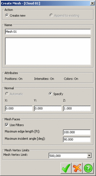
This dialog operates in two different modes: multiple source
mode and single source mode. The single source mode is typically
the result of right-clicking a data object in the PointCloud tree
structure and selecting Create Mesh or from the Action
Tab, this mode only allows the mesh to use the originally
selected data as its source. Use filters determines whether
or not to filter out vertices based on any filters applied to the
source object. The Normal is the direction to use for the
Delaunay mesh triangulation; typically you want to use an axis that
is representative of the direction that the data was taken from,
such as the view direction of the scanner. In the case of scans,
there will be a From Scan radio button that you can use,
which will automatically use the scanner position information from
the scan as the normal. The Mesh Faces panel allows you to
set restrictions on the meshing process. No edge in the mesh will
be created if it will exceed the Maximum edge length or if
the angle between the two faces it connects exceeds the Maximum
incident angle. Mesh Vertex Limits specify the maximum
number of mesh vertices that will be used in a mesh. Setting this
value too low may result in no mesh being created. One can also
create a mesh with multiple sources by right-clicking the
Meshes folder and selecting Add ⇒ New, this will
bring up a dialog similar to the one above with an extra tree
control to the left.

All of the controls on the right half of the dialog are the
same, but you can now toggle inclusion of objects into the mesh by
clicking the red x next to their name in the tree, turning the icon
to a green circle.
Smooth Mesh
The Smooth Mesh command allow you to create a new mesh or modify
the existing mesh. There are two methods for smoothing. They may be
used separately or in combination.
 Smooth
Spikes applies the user values for the parameters to
remove or reduce the number and severity of spikes in the selected
mesh.
Smooth
Spikes applies the user values for the parameters to
remove or reduce the number and severity of spikes in the selected
mesh.
- Spike Slope % is the angle in degrees of the
profile slope required for a vertex to be considered a spike. a
value of 90% will disable this test.
- SD Threshold is the distance from the average
plane based on the surrounding points that qualifies a vertex as a
spike.
- Min Radius is the distance to from a point to
look for the surrounding points.
- Point Adjustment Factor is how far a point
should be moved to bring it into the average plane. 0 is no
movement. 1 is complete movement.
- Passes: Value 1-9. This is the number of times
the process should be run.
- Use Max Length This is an alternative to the
Minimum Radius option and should only be used is there are a
significant number of breaklines in the mesh.
 Average
- Factor is how far a point should be moved to
bring it into the average plane. 0 is no movement. 1 is complete
movement.
- Passes Value 1-9. This is the number of times
the process should be run.
- Steps is the number of vertices to step out
from the current vertex when calculating the average.
- Minimum Distance is the minimum distance a
point must be moved to be smoothed. If the point would be moved
less than this value it is left and not moved.
Mesh Simplification
Simplifying a mesh is one of the key ways to reduce data down to
a state that it can be transferred over to CAD software or to make
it more manageable in PointCloud without losing much surface
quality. Right-click the mesh to simplify and select
Simplify. This will open the Simplify Mesh
dialog.

There are two methods of mesh simplification available. The
Elevation Difference method will loop over all the vertices
in the mesh Passes number of times and each vertex whose
deletion would lead to a deviation in the mesh of less than the
Threshold will be deleted. Elevation Difference is generally
slower. The Edge Cost method determines the total deviation
in the mesh that result from each edge removal (by merging its two
vertices) and removes all edges whose removal would result in a
deviation of less than the Threshold. In addition, the
preserve breaklines options for the Edge Cost method will
multiply the deviation value calculated by the Breakline
Weight if the angle between the two faces it borders is greater
than the Breakline Angle, this can be used to help preserve
corners. The Elevation Difference method is best used in
largely flat data (such as a scan of a large open area), while the
Edge Cost method is best for complex data with lots of
corners. Additionally there is a memory tradeoff, the Elevation
Difference method is generally slower at higher numbers of
passes (which gives better results), while the Edge Cost
method consumes more memory.
Cleaning a Mesh
To remove spikes from a mesh, right-click the target mesh
and select Clean.

Vertices that meet the parameters of this dialog will have their
positions adjusted to meet the shape of the vertices around them,
smoothing out the mesh. These parameters are as follows:
Search Distance determines the distance for a
vertex to search for vertices that exceed the Delta % Slope.
Delta % Slope is the maximum change is slope that is
allowed. Vertices that exceed this value are removed.
Passes determines the number of passes to make over the
mesh.
Resample a Mesh
Resampling a mesh goes through the list of points in a Mesh and
takes one out of each "Step Value" points. Therefore the number of points in
the resulting Mesh will be (1 / Step Size) times the original
number of points in the Mesh.
To run this command, right-click on the existing mesh and
select Resample.
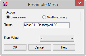
From here, the user can either choose to modify the existing mesh
or create a new mesh with the resampled data.
The Step Value change be varied from 2 to 10, depending on the
final size of the output.
For example:
| Original Mesh
|
Mesh Resampled Step
2
|
Mesh Resampled Step
10
|

|

|

|
Approximate File Sizes
of Exported TIN
|
10Mb
|
5Mb
|
1Mb
|
Tree Folder: Meshes
Prerequisite: An Existing Mesh