
There are two data types in Carlson Point Clouds. These are Instrument Data and Processed Data. Within each data type there are various items and objects that can be added, edited or created. These Data types and items are organized into a tree structure and each can be manipulated by right clicking to bring up a menu specific to that item type. The menu options presented when an item is right-clicked will depend on what the item is. The data types listed here are specific to Instrument Data. Common functions can be found in the Data Objects section.
There are three kinds of point item types in Carlson Point Clouds:
Coordinate Points are processed data and are discussed in the Processed Data section.
Target points always exist as a sub-item of a Scan Position and are in that scan position's local coordinate system. This means that a project can have several sets of target points (one for each scan position).
Control points are the global positions of the target points, and are a sub-item of the Instrument Data folder. There can be only one set of control points for a project.
Reflectors in a Point Clouds project represent a disk, sphere, or cylinder reflector within the set of scans for the current project. Each reflector can be linked to a control point which will enable Point Clouds to account for the shape of target points that are to be linked with that control point during the scan registration process.
These reflectors can either be imported from an ASCII text file with the Import command or entered in manually with the Edit command. Pressing Edit will bring up the Reflectors editor dialog box.
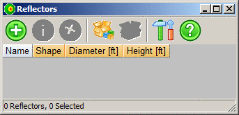
Below is a list of the Reflectors Editor options.
|
|
New Reflector brings up a dialog that allows you to specify the properties of a new reflector to add. |

Name will specify a unique name to be used for the
reflector in the registration process.
Shape is a dropdown with three options relating to the three
reflector shape types (disk, cylinder, and sphere).
Diameter allows you to specify the diameter of the sphere,
cylinder, or disk objects.
Height is accessible only for the cylinder reflector type
and specifies the height of the cylinder.

|
Edit Selected Reflector brings up the Reflectors edit dialog which allows you to change properties of the currently selected reflector. |

|
Delete Selected Reflector deletes the currently selected reflectors. |
| Import Reflectors brings up the ASCII file import dialog. | |

|
Export Selected Reflectors brings up the ASCII file export dialog. |

|
Settings allow you to configure what properties of the reflectors are visible in the spreadsheet control. |

|
Help brings up help documentation. |
After all the reflectors have been added to your project, linking them to their corresponding control points is done through the Control Points Editor.
The Coordinate System is the current transformation applied to a Scan Position. This transformation is applied to any scans that belong to the current scan position. Typically, manual modification of the coordinate system should not be necessary, as the proper coordinate system to align scans properly should be determined during the registration process. To modify the coordinate system for a scan position, right-click it and select View. This will bring up the Coordinate System editor.

The transformation panel displays the transformation matrix that is applied to the scan position. The three buttons along the bottom left are:

|
Register Scan Position Four registration methods are available; Use existing references, Match point names, Match point descriptions and Minimize point position error. If you select Minimize point position error, the Registration Settings panel will activate and you can set Maximum Error, minimum References and toggle Update target point names and Update target point descriptions |
| Import brings up the import dialog box. | |
|
|
Export brings up the export dialog box |
Images are stored in a folder as a sub-item of a scan position. There can be multiple images per scan-folder, and typically are pictures taken from the position of the scanner. Images can only be viewed in 2D mode.

The Files panel specifies the Source and Target location for the image file selected.
The Action panel allows the user to choose to copy the selected image to the target location or move the selected image. Moving the image will delete it from the source location and it will only be available in the target location.
The If target file exists panel determines what to do if the file name of the image being added already exists in the project folder.