There are several data types in Carlson PointCloud. These items are organized into a tree structure and each can be manipulated by right clicking to bring up a menu specific to that item type. Depending on the complexity of the selected object, a menu may not pop up or a menu with several options may pop up.
There are several functions that are shared among several object types. For brevity, these functions are listed here.
In every function that can manipulate a dataset (cleaning, simplifying, etc), the topmost set of options in the dialog for that function consists of options for the results of the change.


Modify Existing will modify the current underlying object in the project, while the Create New will add a new object to the project in the same folder as the object being manipulated, with the Name option specifying the name of the new object.
If an object has external data, such as a cloud, scan, or mesh, it may be useful to preserve the original data in case changes are made to it that are unrecoverable. Selecting Copy will bring up the copy object dialog.

The new item will be added to the same folder as the source item, with the name chosen.
If an object can be removed from the project, there will be a Remove option in the right-click menu for that object. If the object has external files (scans, meshes, and clouds) you will be prompted with what action to take with the external file.
To rename an object, right-click it and select Rename. If you try to assign that object a name that already exists elsewhere in the folder that object is in, PointCloud will revert the change back to its old name.
If an item has data that can be viewed (in either two dimensions or three dimensions), there should be a View option in that objects right-click menu for that object. Upon clicking View, the View Object dialog should be displayed.

The Action panel determines whether to create a new scene for that object or to add the object to a scene that already exists. If Append to existing is selected, the list in the options panel will become enabled to allow selecting the target scene, with Create new selected; the name in the Name panel will determine the name of the new scene. The Mode panel determines the dimensions to view the data in. Viewing the data in 2D mode will only be available if the dataset can be laid out on a two dimensional plane (scans, profiles, and images). Additionally, selecting 2D mode will not add a new scene to the project, it will only create a temporary scene to view the data in, as there is no reason to view multiple objects in the same 2D view (the objects would all obscure each other). The Color panel determines the mode to color the data in, of which there are eight modes that will be available depending on the data in the target object and the mode it will be drawn in. These color modes are divided up into categories based on how the colors are determined, these categories are: Simple colors the entire dataset the same color, Position colors each point based off its world positioning data, Intensity colors each point based off of its single intensity value, Direct colors the points based off their color information.
The Simple category only has the Direct color mode which colors the entire dataset a single color, which can be chosen in the Scene tab of the Project Manager.
The Position color category has three color modes: Elevation which colors each point in a range from blue being the minimum elevation value to red being the maximum color value, Range which colors each point based off its distance from the origin (or scanner if the current object being viewed is a scan), black being the minimum distance and white being the maximum, and Normal which colors each point based of the normal of the surface at that point. In the Normal mode, each color dimension (red, green, and blue) are assigned a spatial dimension (x, y, and z) to represent that direction in the objects finally color.
The Intensity color category has three color modes: Direct will color each pixel in the range from black to white based off its intensity value, Scaled will scale the range of intensities so that the minimum intensity in the data set matches up with zero and the largest intensity in the data set will match up with the maximum possible intensity value, which can make minor changes in intensity more noticeable, and Equalized will perform a similar scaling operation but do it in a manner that will equalize the histogram of the intensity values, making it so that all intensity values occur equally often, this method can also make minor changes in the intensity much more noticeable.
The Color color category has two color modes: Direct, which colors each point directly by its internal color value, and Grayscale which colors each point by the grayscale representation of its internal color value.
In addition to the above method of scene creation, you may also create a scene by right clicking the scenes folder and selecting Create New from the menu. This method will allow you to create a scene with multiple objects in it without having to go through the dialog several times.

The right half of the dialog is the same as single object viewing, but the left half of the dialog shows a tree structure representing objects in the project that can be added to the scene. Click on the red x icon next to an object to toggle inclusion of that object in the scene.
When viewing any of the large object types (scans, meshes, and clouds) there is only one copy of that object retained in memory at all times. This is done to preserve memory as much as possible when opening up multiple views of the same object. This also means that any changes made to the object in one view will be reflected in all other views of that object. For instance, if you're viewing a scan in two views and wish to clean up its data, deleting points from the scan in one view will change the scan in any other views of it. When all views of an object have been closed, the object modified dialog will be displayed prompting the user for an action to perform with the modified data.

This dialog is very similar to the action panel found in many other dialogs. Modify existing will save the changes to the original object and Create new will allow the user to specify a name for a new object of that type with the modified data. Discard Changes will close the scene without saving changes.
If an object can be drawn to the CAD engine that PointCloud is running alongside, there will be a Draw option in the right-click menu for that object. Clicking Draw will bring up the standard Carlson layer selection dialog. Objects will be drawn in their current coordinate system (if two scans are properly registered, they will be properly aligned with each other when drawn to the CAD engine).
There are three kinds of point item types in Carlson PointCloud: control points, target points, and coordinate points.
Target points always exist as a sub-item of a scan position and are in that scan position's local coordinate system. This means that a project can have several sets of target points (one for each scan position).
Control points are the global positions of the target points, and are a sub-item of the Instrument Data folder. There can be only one set of control points for a project.
Coordinate points are points extracted from the final registered data sets and are a sub-item of the Processed Data folder. Coordinate point positions are in whatever coordinate system the data the extraction is performed from is in.
All point types have the same right-click menu options.
Polylines are usually extracted from the registered data, but they can also be imported or manually entered with the Import and Edit commands. Polyline importation is very similar to importing a set of points; see the documentation for data points for more information. The edit brings up the Point Editor; see the documentation on the point editor for more information.
Reflectors in a PointCloud project represent a disk, sphere, or cylinder reflector within the set of scans for the current project. Each reflector can be linked to a control point which will enable PointCloud to account for the shape of target points that are to be linked with that control point during the scan registration process.
These reflectors can either be imported from an ASCII text file with the Import command or entered in manually with the Edit command. Pressing Edit will bring up the point editor dialog with some specialized options for reflectors.
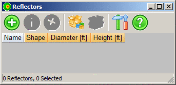
The only difference between this point editor and the one used for the various point objects is that the Add Reflector button will bring up a different dialog that allows you to specify the properties of the new reflector.

Name will specify a unique name to be used for the reflector in the registration process.
Shape is a dropdown with three options relating to the three reflector shape types (disk, cylinder, and sphere).
Diameter allows you to specify the diameter of the sphere, cylinder, or disk objects.
Height is accessible only for the cylinder reflector type and specifies the height of the cylinder.
After all the reflectors have been added to your project, linking them to their corresponding control points is done through the control points editor. See the documentation for the Point Editor for more information.
Images are stored in a folder as a sub-item of a scan position. There can be multiple images per scan-folder, and typically are pictures taken from the position of the scanner. Images can only be viewed in 2D mode.
The Coordinate System is the current transformation applied to a Scan Position. This transformation is applied to any scans that belong to the current scan position. Typically, manual modification of the coordinate system should not be necessary, as the proper coordinate system to align scans properly should be determined during the registration process. To modify the coordinate system for a scan position, right-click it and select edit. This will bring up the Coordinate System editor.

The transformation panel displays the transformation matrix that is applied to the scan position. The three buttons along the bottom are Register Scan Position, Import, and Export, from left to right. See the documentation on the Point Editor for information about these functions.
A contour item consists of several contour polylines that have been extracted from a mesh. Contour objects can only be viewed in 3D mode and drawn to the CAD engine. Contour extraction is done through the Action Tab, for more information on how to extract contours, see the documentation for Extract Contours in the Action Tab.
Grids are rectangular representations of a cloud typically used to instead of TIN. The grid file that is created by Point Cloud has a PCG extension. Point Cloud grids are saved to the Grids folder under Processed Data in your project folder. To share grids created in Point Cloud with other Carlson modules right-click the grid you want and select export. A GRD file will be exported. Grids created in other Carlson modules can be imported into Point Cloud by right-clicking Grids and selecting Import. For more information on how to create a grid, see the documentation for Create Grid in the Action Tab.
A profile consists of a set of height values and distances taken along a polyline extracted from a mesh. Profiles can be viewed in 2D and 3D mode and drawn to the CAD engine. Additionally, profiles can be extracted to the .pro file format. Profile extraction is done through the Action Tab of the Project Manager. For more information on how to extract profiles, see the documentation for Extract Profile in the Action Tab.
A section object consists of a list of profiles taken at certain distances along a polyline. Sections can be extracted from a mesh using the Action Tab in the Project Manager. Sections can only be viewed in 3D mode and can also be drawn to the CAD engine. Additionally, sections can be extracted to the .sct file format. See the Extract Section documentation in the Action Tab for more information about how to extract sections.
Scene objects maintain a list of objects that are in the scene, graphics properties for those objects, and camera information for the scene. If a scene is closed and then reopened, these properties should still be the same.