Clicking the Bare Earth button will expand the Bare
Earth panel and put the Current Mode into Bare Earth
mode.
There are two modes for Bare Earth extraction, Profile
Mode and Grid Mode. Profile mode works by drawing
a 3D line away from the scanner and seeing if it slopes upwards too
sharply, removing any vertical segments and keeping any flat
segments. Grid mode works by inspecting the cloud as a grid
to find the lowest valid points in each grid cell and keeping only
those points.
For Profile Mode: When you move your cursor to the Scene window Point Cloud is ready for you to specify the "scanner" position or center of the Bare Earth extraction. The scene must be in plan view to run the Bare Earth extraction in Profile Mode. Points are examined and either included or excluded for the Bare Earth Cloud based on the extraction parameters.
There are several options that will affect this type of Bare Earth extraction.
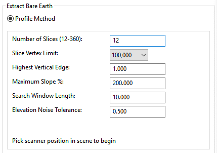
Number of Slices (12-360) - This value determines the number of division of a 360 degree circle to use when extracting the Bare Earth. The default value of 36 uses 10 degrees in each slice.
Slice Vertex Limit - This is the maximum number of points that will be used in each slice. The total number of points used to generate the Bare Earth result is the Vertex Slice limit times the number of slices.
Highest Vertical Face - This value should be equal to the highest vertical feature in the ground surface plus a little extra for some tolerance. For example, if the highest vertical edge is a 6 inch curb, then you should enter something like 0.75 to capture the curb with a bit of a buffer. The program removes points that exceed the Highest Vertical Face value.
Maximum Slope % - This value should be equal to the steepest slope in the ground surface plus some extra for tolerance. For example, if the steepest ground slope is a 2:1 side slope, then use something like 60 (50% plus a 10% buffer). The program removes points that exceed the Maximum Slope % value.
Search Window Length - This is how far from each data point that the program will check other data points for the Highest Vertical Edge and Max Slope criteria.
Elevation Noise Tolerance - This should be the expected elevation tolerance of the point measurements. For example, use 0.1 when the data point elevations are within +/- 0.1 of the target surface. The program removes data points that are isolated and higher than this elevation tolerance from their neighbors.
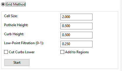
Cell Size: The grid used for this will use square cells with this dimension.
Pothole Height: The tolerance for a point to be considered within the level that is to be kept for each grid cell.
Curb Height: The tolerance between adjacent cell elevations to determine which cells should be kept.
Low-Point Filtration: Filters out points below the level for each grid cell. A value of 0 will just accept the lowest point in each cell even if it's an outlier due to noise.
Cut curbs lower: When this is checked, doesn't take adjacent cells into account when deciding which points to take from each grid cell.
Add To Regions: Creates regions within the current Cloud instead of creating a new Cloud. Regions are usually slower than creating a new Cloud.
Specify Scanner Position: -Ctrl-Click in the Scene window-
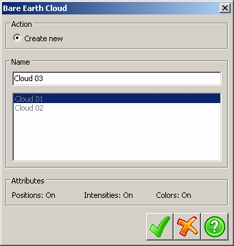
A default name will be provided for the new cloud being created based on the Name Conventions under Settings. You may change the name by typing in the Name field.

|
Accepts the new cloud file name and begins the Bare Earth Extraction. |

|
Cancels the file creation and the Bare earth extraction. |

|
Accesses the Bare Earth Extraction help file. |
Tab Location: Action Tab
Panel and Button: Extract and Bare Earth
Prerequisite: Open Point Cloud Scene in plan view