|
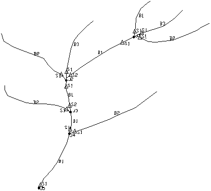
| Example of labeled SEDCAD structure layout |
This command is the third and final step for creating the SEDCAD layout. Label Structure Layout draws text labels for the junctions, branches, and structures in the network. A junction, branch, and structure report is also generated. Flow polylines and structure symbols must be drawn before running this routine. This command uses the labeling rules as described in the SEDCAD manual.
Symbol size <4.0>: press Enter
Junction offset tolerance <10.0>: press Enter
Flow lines that meet the main branch within this distance of each
other are considered the same junction.
Select flow polylines and structure symbols.
Select objects: pick the polylines and symbols
J5,B1,S1
J4,B2,S1
J4,B1,S1
J3,B2,S1
J3,B1,S2,S1
J2,B2,S1
J2,B1,S2,S1
J2,B3,S1
J2,B1
J1,B2,S1
J1,B3,S1
J1,B4,S1
J1,B1
Write report to file (Yes/<No>)? press Enter
Write report to printer (Yes/<No>)? press Enter
|
|
| Example of labeled SEDCAD structure layout |
Pulldown Menu Location: Watershed > SEDCAD Structure
Layout
Keyboard Command: sedcad3
Prerequisite: flow polylines and structure symbols