The AutoCAD/IntelliCAD engine stores the values for its operating environment and some of its commands in system variables. Each system variable has an associated type: integer, real, point, switch, or text string. This command allows you to list or change the values of system variables.
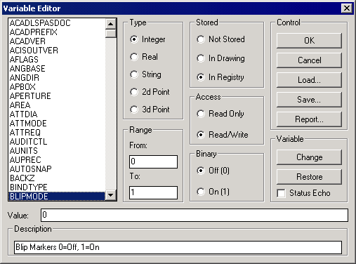
● List Box: Contains a list of the variables associated with the currently running version of AutoCAD. There are more items than will display on the list box, use the scroll bar to move up and down through the list. Picking on an item in the list box makes it the current item, causing the information about the item to be displayed, and can be affected by most of the edit commands explained below.
● Edit Field: When an item on the list box is picked, its current setting is displayed in the edit field. If you intend to make changes in an item, use standard editing procedures including the use of arrow keys and/or pointer movements to make changes. Once changes have been made, you must use the CHANGE options explained below to effect changes. Pressing enter at the edit field will have no effect on the item in the list. If the item selected is a read-only variable, the edit field will be grayed-out and will not allow input.
● Description: When an item on the list box is picked, its definition is referenced and displayed in this field. This can be a benefit in learning the uses of the assorted system variables. This is a display only field, so you can't change the description given.
Under Type Group, the type of variable will be displayed indicated by one of the radio buttons. Each of these types are explained below for your benefit. For additional information on variable types used by AutoCAD, obtain and consult a source of AutoCAD documentation.
● Integer: Defined as a whole number in the range from -32767 to +32768, no decimal value accepted.
● Real: Defined as a real number in the range from -1.797E+308 to +1.797E+308, with extreme decimal accuracy maintained.. Some real variables have a smaller range than previously stated.
● String: Defined as a sequential array of characters in the range from 0 to 65535 characters, with a range of ASCII (0-255). Numbers can be included in strings, even though they have no mathematical significance.
● 2D Point: Defined as a list of two real numbers in the range from -1.797E+308 to +1.797E+308 separated by a comma, having extreme decimal accuracy maintained. Always maintain the X,Y format, one (and only one) comma must be used, separating the X and Y.
● 3D Point: Defined as a list of three real numbers in the range from -1.797E+308 to +1.797E+308 separated by commas. While editing a 3D point, you must always maintain the X,Y,Z format, two (no less or no more), commas must be used, separating the X and Y and Z values.
Under Range Group, the variable displayed will usually have a range displayed. The FROM value indicating the minimum, and the TO value being the maximum value accepted.
Under the Store Group, depending on the type of variable, AutoCAD may store the value in the drawing or the configuration file, or it may not be stored. Each of these types are explained below for your benefit.
● Not Stored: Some variables, such as PLATFORM and CDATE, are not stored because they are system interdependent.
● In Drawing: Most variables are stored in the drawing, making the drawing format more personal than just a database of objects. This allows you to open a drawing and have it behave just as though you had never left it.
● In Config: These are variables that remain the same regardless of the drawing opened. APERTURE and PICKBOX are just two examples of variables stored in the configuration file.
Under Access Group, depending on the type of variable, AutoCAD may not allow you to make changes to it. Each of these types are explained below.
● Read Only: Some variables, such as PLATFORM and CDATE, are read-only and therefore cannot be changed. Read-Only variables are marked and the edit field will be grayed indicating that you can't change the variable.
● Read/Write: Most variables are read/write and can be changed. These variables are marked and the edit field will be active so you can change the variable.
Under Binary Group, depending on the type of variable, the value may be off or on, yes or no. If the variable type is not binary, this group will be grayed out entirely.
● Off (0): Indicate an off condition. Some variables, such as ATTREQ, are simply on or off toggles. You may change a binary item by clicking in this group to change the variable, or changing the value in the edit field.
● On (1): Indicate an on condition. Binary variables are simply on or off toggles. Their range is from 0 to 1. You may change a binary item by clicking to change the variable, or changing the value in the edit field.
Control Buttons - These buttons are the main controls in the use of the Variable Editor. Each buttons purpose is explained below.
● OK: Used to accept the changes made during the variable editing process, returning you to the command prompt with changes in effect.
● Cancel: Used to cancel the changes made during the variable editing process, returning you to the command prompt without the changes in effect.
● Load: Used to load a saved set of system variables. This allows you to create a drawing, save the system variables, open a second drawing, and load those variables into that drawing. Read-only variables are skipped.
● Save: Used to save the current system variables to a disk file. All system variables are stored to the file, even those that are marked as read-only.
● Print: Used to print the current system variables. After choosing this option, you will prompted for an output filename, then the program will proceed to write the system variables to the file. This file can be loaded into any editor or word processor, edited and printed.
Variable Buttons - These buttons are used to control the changes in variables, while using the Variable Editor. Each buttons purpose is explained below.
● Change: Used to execute the changes typed into the edit field. You must use this button, simply pressing enter will not make the change.
● Restore: Used to cancel the changes typed into the edit field. If you make a mistake or change your mind while making changes in the edit field, press this button to restore the edit field to the value before editing.
● Status: Used to determine if the program will echo the status of changes being made to the command area. If this toggle is on, any changes made from the dialog will echo the change. Also if a stream of change commands is being read from a file, and the toggle is on, the changes taking place will be displayed.
Note: This command displays many more system variables than are found in the Systems Variable Chapter, which contains a list of supported system variables. Modification of any system variable other than the supported ones found in the Systems Variable Chapter is done at your own risk, and may result in program errors requiring a re-installation of Carlson.