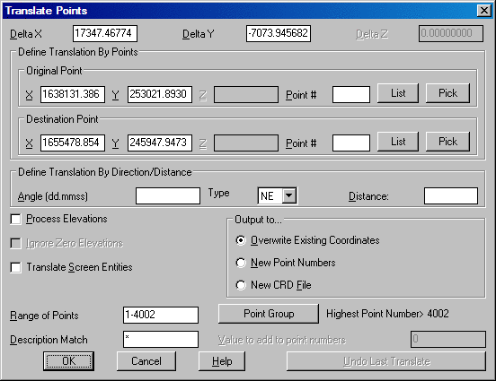
This command translates points in a coordinate file from one
coordinate position to another. The delta X, Y, and Z can be
entered directly or calculated from original and destination
coordinates. The original and destination coordinates can be
entered directly, specified by point number, selecting the point
number from a point list by selecting the list icon, or selected
from the screen by selecting the pick icon. Once these points have
been specified, the Delta X,Y,Z, if Process Elevations is checked
ON, fields will be filled in with their calculated values. Any
points in the drawing will be updated automatically in addition to
updating the coordinate file.
Define Translation By Angle/Distance requires a specified direction, Northeast (NE), Southeast (SE), Southwest (SW), Northwest (NW) or Azimuth (AZ) along with a specified distance in order to perform a translation. Once the direction and distance are entered, the Delta X,Y,Z will be calculated. This is a useful command when you know that the job needs to shift, for example, to the Northeast 25 degrees for a distance of 100 feet. Here you would simply type in 25 in the Angle (dd.mmss) field, choose NE in the Type field and then enter the distance of 100 in the Distance field.
With Process Elevations
checked, all elevations will be translated by the specified or
calculated Delta Z value. This option is very useful in correcting
point elevations after performing a survey with assumed elevations
and then later surveying into a benchmark with known true
elevation. In this case only the Delta Z value, use (-) to indicate
a lower correction, and the range of points to translate would be
required for a translation. For example if the entire job needed to
be lowered by 5', the Delta Z would be defined as -5 and the Range
of Points defined as ALL.
Ignore Zero Elevations
is only available when Process Elevations has been chosen. With
this option checked ON, all points with an elevation of 0 will be
ignored resulting in no translation taking place on these
points.
With Translate Screen
Entities checked ON, after specifying the point range or
group to translate and selecting OK on the dialog box the following
command line prompt is displayed:
Select objects to rotate (points excluded):
At this prompt select the objects on the screen, polylines, lines,
arc, etc., to also translate and press enter. The translation of
the points and screen entities will be completed.
Various Output Options for the translated points are available.
Overwrite Existing Coordinates will overwrite the existing coordinate points with the new translation coordinates thus changing the coordinate values in the existing crd file.
New Point Numbers will assign new point numbers to the translated coordinate points and leave the original coordinate points unchanged and present in the coordinate file. When using this option, on the Range of Points to Translate dialog, there is a Value to add to point numbers field. In this field, enter the value to add to the point numbers. For example if the existing point numbers are 1-20, and the value to add is 100, the resulting new point numbers will begin at 101 and end at 120.
New CRD File will place
the translated coordinates in a new crd file. After selecting OK to
the range of points to translate dialog, the Coordinate File to
Create dialog will appear. On this dialog enter the name of the new
crd file and select save. The original crd file will remain
unchanged and the new file will contain the points with the
translated coordinates.
Specifying the points to be translated is accomplished either by
specifying a Range of
Points (1-20,33,36-40....) or by Point Groups. If using the Point Group
option, the Select Point Group(s) dialog box will be displayed
allowing for the selection of the Group(s) to rotate.
The Description Match
option only translates points with the description(s) specified in
this field.
Undo Last Translation restores the points to their previous location before translation. It is important to note that if Translate Screen Entities has been checked to restore the translated objects to their previous location will require the use of the undo command located in the Edit pulldown.
The AutoCAD command MOVE can be used to translate points on the screen but this does not update the coordinate file unless you have the option Link Points with CRD File turned ON in Configure . (Note: This toggle must have been turned ON prior to locating the points). If you do use the MOVE command and the CRD file needs updating, run the command Update CRD file From Drawing found in Coordinate File Utilities.
Pulldown Menu Location: Points
Keyboard Command: transpt
Prerequisite: points in a coordinate file