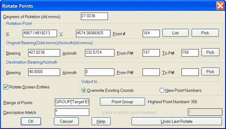
This command rotates points in a coordinate file. The degrees of
rotation can be entered directly or calculated from original and
destination bearings or azimuths.
The Rotation Pointwill remain unchanged while the points
specified for rotation rotate around it. This point can be
specified by using the List button to pick from a list of
points contained in the coordinate file, or from the screen by
using the Pick button. The
rotation point can also be defined by a coordinate value by
manually entering in the X and Y values of the point. This point
must be defined before the rotation will take place.
The Original
Bearings/Azimuths and
Destination Bearings/Azimuths can be entered
directly or specified by point numbers. If using a pair of points
to define the original bearing and then specifying the destination
bearing by entering in the desired Bearing/Azimuth, the From and To
Pt# fields should be left blank in the destination bearing/azimuth
settings. Use the From and To Pt# fields in the Destination
Bearing/Azimuth when you want to make a direction or
Bearing/Azimuth between two existing points match the
Bearing/Azimuth between two other existing points within the file.
For example, to make the bearing between points 10-12 match the
bearing between points 25-26, the Original Bearing/Azimuth could be
defined as From Pt#10 To Pt#12 with the Destination Bearing/Azimuth
defined as From Pt#25 To Pt#26.
With Rotate Screen
Entities checked ON, after specifying the point range or
group to rotate and selecting OK on the dialog box the following
command line prompt is displayed:
Select objects to rotate (points excluded).:
At this prompt select the objects on the screen, polylines, lines,
arc, etc., to also rotate and press enter. The rotation of the
points and screen entities will be completed.
Various Output options for the rotated points are available.
Overwrite Existing Coordinates will overwrite the existing coordinate points with the new translation coordinates thus changing the coordinate values in the existing crd file.
New Point Numbers will
assign new point numbers to the translated coordinate points and
leave the original coordinate points unchanged and present in the
coordinate file. When using this option, on the Range of Points to
Translate dialog, there is a Value to add to point numbers field.
In this field, enter the value to add to the point numbers. For
example if the existing point numbers are 1-20, and the value to
add is 100, the resulting new point numbers will begin at 101 and
end at 120.
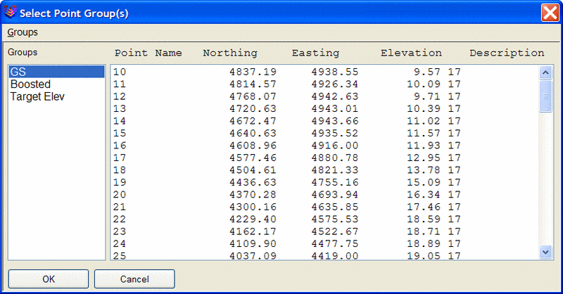
Specifying the points to be rotated is accomplished either by specifying a Range of Points (1-20,33,36-40....) or by Point Groups. If using the Point Group option, the Select Point Group(s) dialog box will be displayed allowing for the selection of the Group(s) to rotate.
The Description Match
option only rotates points with the description(s) specified in
this field.
The points that have been specified for rotation that are present in the drawing will be graphically updated to their new location in addition to an automatic update of the coordinate file.
Undo Last Rotate
restores the points to their previous location before rotation. It
is important to note that if Rotate Screen Entities has been
checked to restore the rotated objects to their previous location
will require the use of the undo command located in the Edit
pulldown.
Pulldown Menu Location: Points
Keyboard Command: rotatept
Prerequisite: points in a coordinate file