Transforms coordinates between local, State Plane 27, State Plane 83, Latitude/Longitude, Universal Transverse Mercator (UTM) and many other projections, including regional and user-defined projections. This works on individually entered coordinates, by range of point numbers and with on-screen entities. For converting between State Plane 27 and 83 within the USA, Carlson calls upon NADCON from the National Geodetic Survey to apply the Latitude/Longitude adjustment. Converting between NAD27 and NAD83 for Canada is supported using NTv2 grids.
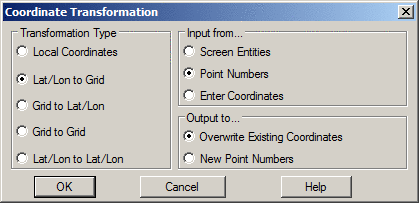
The Transformation Type is used to define the Source Coordinate and Destination Coordinate formats. Settings for Lat/Long Datum, Lat/Long formats (dd.mmss or dd.dddd), Projections, State Plane Zones and coordinate units are defined in the Transformation Type dialog. The format of this dialog will change depending upon the type of transformation requested.
For Grid to Grid transformations, the program converts between state plane projections as well as other pre-defined and user-defined. When converting between pre-defined/user-defined projections, the program automatically converts the source grid coordinate to latitude/longitude and then to the destination grid coordinate. This method of using latitude/longitude works for converting between projections that share the same datum.
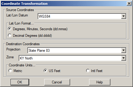
Example Lat/Long to Grid dialog
For all Transformation types, there are three options for inputting the data to be transformed. Data can be selected from the screen by using the Screen Entities. If a range of points or a particular point is desired, the Point Numbers option would be used. Manual entry of coordinates to transform one at a time is accomplished with the Enter Coordinates option. The coordinates can be typed in or use the Input Point Number option. Output Point Number is an option to store the results in the coordinate file.

For all transformations there are two output options when using point numbers as the input data. Overwrite Existing Coords replaces the original coordinate values with the new coordinate values after transformation. New Point Numbers will retain the original coordinate data and point numbers and create new point numbers with the revised coordinate data after transformation.
When transforming a Local Coordinate System, there are three options for defining the transformation as shown in the next dialog.
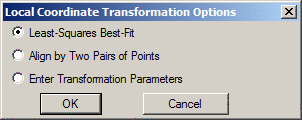
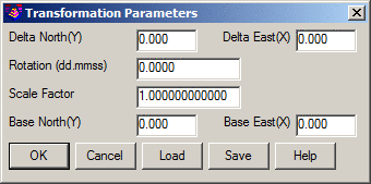
The Enter Transformation Parameters method prompts for the translate, rotate and scale parameters. The Base X and Y are used for the rotation and scale. The Load and Save functions store and recall the parameters to a .DXY file.
The Align by Two Pairs of Points option uses two pairs of source and destination coordinates. The first pair defines the translation as the difference between the source and destination northing and easting.
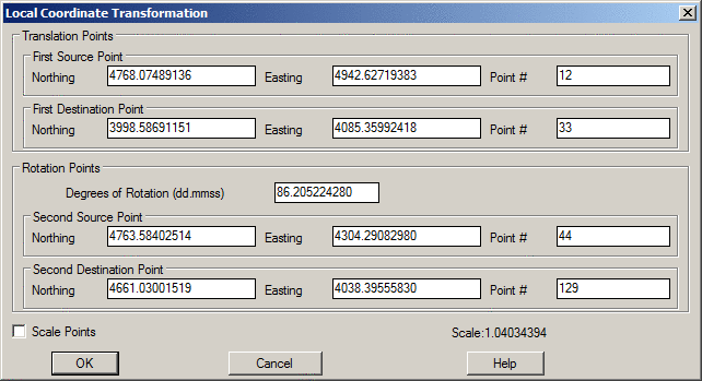
This destination point is also the pivot point for rotation. Rotation can be entered directly or defined by a second pair of points where the bearing between the first and second source points is rotated to align with the bearing from the first and second destination points. There is an option to also apply scaling. The scaling holds the angle between points and adjusts the distances by the scale factor. The scale factor is calculated for each point as the elevation factor at the first source point times the grid factor at the first destination point averaged with the elevation factor at the transform point times the grid factor at the transform point.
The Least-Squares Best-Fit option is used when there are more than two pairs for translation points. Since two pairs of points are sufficient to define the translation and rotation, more than two pairs of points provides more than enough information.
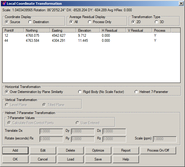
Over Determination by Plane Similarity is used to find the least squares best fit transformation for all the given source and destination points. Besides doing a translation and rotation, this option will also scales the points during the transformation. The Rigid Body Transformation also does a best fit least squares transformation, but applies only translation and rotation with no scale. The Helmert 7-Parameter method can also be used for local transformations. The 7-Parameter Values can be calculated from control points or entered by the user.
The Transformation Type chooses between doing a 2D transformation and 3D transformation. For the 3D transformation, the program transforms the x/y using the same method as the 2D transformation, and the z is transformed using an elevation difference model that is modeled by either a best-fit level plane or tilted plane as set by the Vertical Transformation setting.
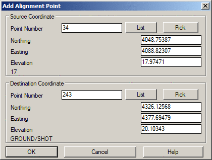
The Add button is used to define the source and destination coordinates for the points that define the transformation. Pressing this button brings up the following dialog box.
The Edit button is used to edit existing data.
The Delete button removes the source and destination pairing from the transformation setup.
The Process On/Off button allows source and destination pairings to be turned on and off. This is useful when wanting to inspect different results using different pairings.
The Optimize option chooses which point pairings would yield the best transformation results by turning off the processing of pairings with higher residuals. This minimizes the average residual for the control points.
The Report option displays a report of the transformation point pairings, their residuals, processing status, transformation scale and avg. residual.
The Load and Save options allow for saving and recalling local coordinate transformation pairings and settings.
Pulldown Menu Location(s):
Points
Keyboard Command: cfutransform
Prerequisite: Drawing entities or coordinate
points