This command guides you to the catch point where the cut/fill slope intersects the existing ground. Coordinates from the GPS receiver or total station are used to model the existing ground. There are four methods for defining the cut/fill slopes:
Design Files
Section File
User Entry
3D Polyline
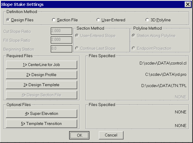
Design files include a centerline file (.cl), profile file (.pro) and template file (.tpl). The centerline defines the horizontal alignment, the profile defines the vertical alignment and the template defines the cross slopes and cut/fill slopes. Superelevation (.sup) and template transitions (.tpt) files can also be used. Using the design files, any station along the centerline can be slope staked. These design files can be created with commands in the Roads menu.
Section files (.sct) can be used instead of design files when
the road is too complicated to model using design files. For
example, if the road contains special ditches at various offsets
and varying lane widths, then it may be easier to enter a final
section file than to define the template and template transitions.
A section file consists of offset-elevation points at different
stations. At a minimum, each station should contain the pivot point
offset-elevations. The slope staking routine will start the
cut/fill slope from the furthest offset point in the
section.
For example, when staking the right side, the right most offset will be used as the pivot point. The section file can optionally contain additional offsets such as centerline and edge of pavement. The program can then report the horizontal and vertical distances from the catch point to these additional offsets. The section pivot offsets can also be assigned a description which the program reports before starting the slope staking. For example, a pivot offset could be "2:1 from flat bottom ditch" which is reported to the operator. When using section files, a centerline file is also required to establish the horizontal alignment. Any station along the centerline can be slope staked because the program will interpolate between entered section stations. The cut/fill slopes from the section can be either User-Entered or Continue Last Slope. The User-Entered option will use the cut/fill slope ratios as entered in the dialog. The Continue Last Slope option will use the last two points in the section file as the cut/fill slope. This Continue Last Slope option applies to section files that contain pivot point to ground segments whereas the User-Entered option is for section files that end at the pivot points.
User entry is a simple method for slope staking that only requires a centerline file. With this method, the program prompts for the cut/fill slopes and the pivot offset and elevation. The program finds this offset-elevation for the stake station along the centerline and begins the cut/fill slope from this point.
The 3D Polyline method uses a 3D polyline for both the horizontal and vertical alignments. The program will prompt you to select the 3D polyline from the drawing. There are two polyline methods. The Station Along Polyline method does slope staking perpendicular to the polyline like the other slope staking methods. The Endpoint Projection is a special method that slope stakes from the selected end of the polyline. This method is described at the end of this section.
The first dialog in Slope Staking chooses the design method. For Design Files method, the files are specified in this dialog. For the other methods, the cut and fill slope ratios are also defined in this dialog.
The next dialog sets the station to slope stake. The station
should be entered as a number without the "+" symbol. For the 3D
Polyline method, the starting station of the polyline is specified
in the first dialog. For all the other methods, the starting
station of the alignment is set in the centerline file. The Next
Interval field is used to increment the stakeout station for the
next stakeout point. The Read Current Position button will take a
measurement from the GPS or total station to find the station of
your current position. This current station is put in the Station
field. The Pick Point button will prompt you to pick a point in the
drawing view. The station of this point is used to fill out the
Station field. For the User-Defined method, this dialog also
contains the offset and elevation of the pivot point. For the 3D
Polyline method, this dialog also contains the pivot point offset
and vertical offset from the 3D polyline to the pivot
point.


For the design file method, the centerline elevation at the stakeout station is calculated using the design profile and then the template is applied to calculate the pivot point. For the section file method, the pivot offset is interpolated from the section file. For example, if the stakeout station is 75 with offset right and the section file has offset-elevation of 18.0 right, 100.0 elevation at station 50 and has 20 right, 102.0 elevation at station 100, then the pivot offset for station 75 would be 19.0 right, 101.0 elevation. For the user entry and 3D polyline methods, the pivot point is specified Station For Slope Stake dialog.
After the slope stake station and pivot point are specified, Carlson Field begins to read the GPS receiver or total station to get the current position. The existing surface to tie into is defined by the elevations from these current position coordinates. The point where the cut or fill slope from the pivot point intersects the existing ground is called the catch point. As each coordinate is read, an existing surface cross section is built and the catch point is calculated. Carlson Field will automatically determine whether to find the catch point on the right side or left side of the centerline depending on the side of your current position. The program displays, in real-time as you move, the northing-easting and station-offset-elevation of your current position and the offset of the catch point. The distance from the current position to the catch point is reported as the offset difference as either "IN" or "OUT". The OUT means you should move out from the centerline. The IN means that the catch point is closer to the centerline. Based on this offset difference, you move perpendicular to the centerline either towards or away from the centerline to reach a new offset from the centerline while maintaining approximately the same station. The difference between your current station and the stakeout station is reported as the "UP" or "DOWN" distance. The UP means that your current station is less than the stakeout station and you should move up the centerline. Likewise, the DOWN means that your current station is greater than the stakeout station and you should move back down the centerline.
When the catch point is located, press the Store button to end the slope staking. A report dialog is then displayed. The Catch Pt is the actual station, offset and elevation of the target catch point. The Stake Pt is the as-staked station, offset and elevation of your current position. The dialog also reports the horizontal and vertical distances from the catch point to the pivot point and the other template points. The Store Catch Point option will record the as-staked coordinates of the catch point to the current coordinate file. The Stake Offset Point is an option to locate an offset point. The offset to stake can be entered as a distance from the catch point or as an offset from the centerline.


To locate the offset point, the same stakeout function from the Stakeout command is used. This function will guide you to the offset point. When the offset is reached, pick the Store button. Then an Offset Point Report dialog pops up containing the station, offset and elevation of the offset point and the horizontal distance, vertical distance and slopes from the offset point to the catch point, from the catch point to the pivot point and from the pivot point to the template points.
After locating the offset point, the station to stakeout dialog appears. You can enter the next station to stakeout or pick the Exit button to end Slope Staking.
Endpoint Projection
This is a special case of the 3D Polyline method that slope stakes from the end of the polyline. The program will prompt to pick a polyline and the end to stake from is the end nearest to the pick position. The direction of slope staking is in the direction of the polyline as if extending the polyline. The program prompts for the elevation of the pivot point which defaults to the elevation at the polyline endpoint. There is also an option to offset the pivot point along the polyline back from the endpoint.
After the pivot point is specified, the program starts the stakeout routine to guide you to the catch point. Then there is a report to show the difference between the staked and the calculated catch point.


Pulldown Menu Location: Roads
Prerequisite: A centerline file or 3D polyline