
Selecting the Equipment Setup command will send the user directly to a settings window that corresponds with the instrument selected in Configure Field. Equipment Setup for total stations will be discussed first, followed by GPS equipment.
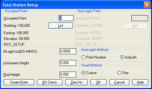
This function for Total Stations lets you tell Carlson Field how you have positioned your total station. The setup information in this command is required before taking shots. Besides running this command from the Field pull-down menu, you can also reach this command with the Setup(F3) button from many of the other Carlson Field functions.
Occupied Point refers to the point your total station is setup on. This point is defined by a point number that references the current coordinate file. The coordinates and description of this point are displayed below the point number. The List button will bring up a list of the points in the coordinate file which you can review or select from. If the coordinates for the occupied point are not yet in the coordinate file, then you can pick the Create Point button to enter these coordinates.
The backsight can reference either a point or an azimuth. Backsight Point is only used if Point Number is selected as your Backsight Method. If you want to use an azimuth instead of a backsight point, select the Azimuth toggle and specify the azimuth in the Bksight Azi box.
Set the Instrument Height and Rod Height. These values will use whatever units your drawing uses: feet or meters.
Carlson Field expects the instrument to have the horizontal
angle zeroed on the backsight. Part of the station setup procedure
needs to include zeroing the instrument on the backsight. To do
this, first specify the occupy point and backsight in this dialog.
Then orient the instrument to the backsight and pick Zero Hz
to zero the gun.
The BS Check button runs a backsight check. The program will take a shot and compare the calculated point to the expected backsight point and report the results to you. This will help you establish if the point you are using as the backsight point is really the point that you think it is. For some robotic total stations, the Backsight Check routine has an option to automatically turn the instrument to the backsight. Then after the check is done, the instrument can be automatically turned back to the previous direction. The purpose of this auto turn is to speed up the steps to check the backsight in the middle of surveying points in a different direction.
For some types of total stations, the Total Station Setup dialog will also contain different options that are specific to that type of total station.
Geodimeter Total Station Setup
The three methods of connecting to the Geodimeter include: Station, RPU and GeoRadio. The Station option is for connecting directly to the instrument. The RPU is a remote control panel. The GeoRadio is a radio for remote control of the instrument. For the GeoRadio, the Station Address and Remote Address set the radio addresses and the Radio Channel sets the radio channel.

The intensity of the instrument Tracklight can be set to Off, Low or High.
The Geodimeter On and Off buttons are for putting the instrument in sleep mode to save power.
There are four different read methods. STD mode has a 3.5 second measurement time for each point. It is usually used when a normal degree of angle and distance accuracy is required. TRK mode uses automatic, measured values that are updated 0.4 seconds after making a contact with the prism. Rep STD mode measures distance automatically every 4 seconds. Fast STD mode measures distance in 1.3 seconds. It is used when the demands on precision are low.
Leica Total Station Setup
The Connection Mode chooses between connecting Carlson Field directly to the instrument or to a radio for remote control.
The EDM Mode sets the instrument distance measurement mode for standard shots. All the possible modes are listed in this dialog including tracking and reflectorless. Be sure to choose a mode that is supported by your instrument. When using the reflectorless mode, the Rod Height should typically be set to zero. When tracking is selected in Carlson Field functions, the program will automatically put the instrument in IR Rapid Tracking mode during tracking and then return to the specified EDM Mode when tracking is done.
The intensity of the instrument Tracklight can be set to
Off, Low, Medium or High.
Laser Pointer allows
the user to toggle the instrument's laser pointer on and off, if
the instrument is so equipped.
ATR (Auto Target
Recognition) allows the user to choose whether or not to use
the instrument's ATR system, if the instrument is so
equipped. This option is not available when using a
reflectorless EDM mode.
Use Instrument Series
to select the proper Leica TPS model you are using. There are
only two choices: 1200
(which uses the GeoCOM protocol) or 100/300/400/700/800/1000/1100 (which
uses the GSI protocol).
The Robotics button can
be used to access the joystick screen, where the user can access
convenient controls for robotic total stations.


Topcon 800A/8000 Direct Total Station Setup
The Read Method sets the instrument distance measurement mode for standard shots. When tracking is selected in Carlson Field functions, the program will automatically put the instrument in Coarse mode during tracking and then return to the specified EDM Mode when tracking is done.
 Topcon 800A/8000 Remote Total Station
Setup
Topcon 800A/8000 Remote Total Station
Setup
The Radio Type can either be Satel 3AS, Satel 2AS,
RC-2, Stream, or Other. With Other, Carlson Field does not send any
radio setup commands. So these radios must be configured before
running Carlson Field. For the Satel 3AS radios, you can set the
radio frequency by Channel ID or by manually typing a frequency
between 468.5 and 470.5. Stream can be used in any situation
where Other would be used. However, Stream is different in
that the instrument streams measurements to Carlson Field thereby
decreasing the probability of a failed reading. It should be
noted, if Stream is used over a very poor radio connection, it is
possible for Carlson Field to get out of sync with the instrument
and fail to stop streaming when needed.
The EDM Mode sets the instrument distance measurement mode for standard shots. When tracking is selected in Carlson Field functions, the program will automatically put the instrument in Coarse mode during tracking and then return to the specified EDM Mode when tracking is done.
Wait Time is switched on when the instrument cannot track a prism due to an obstruction. If after the wait time have elapsed the instrument does not switch back to tracking mode, then searching mode is set.
Vertical range and Horizontal range set the search area. Vertical range can be anywhere from 0-90 degrees, and horizontal range can be anywhere from 0-180 degrees.
Track Indicator On if checked turns on the light which is mounted below the telescope.
Joystick Speed sets the instrument turning speed from the
arrow keys in Robotic control.
 Topcon APL1/APL1A Total Station
Setup
Topcon APL1/APL1A Total Station
Setup
The Radio Type can either be Satel 3AS, Satel
2AS or Other. With Other, Carlson Field does not send any radio
setup commands. So these radios must be configured before running
Carlson Field. For the Satel 3AS radios, you can set the radio
frequency by Channel ID or by manually typing a frequency between
468.5 and 470.5.
The EDM Mode sets the instrument distance measurement mode for standard shots. When tracking is selected in Carlson Field functions, the program will automatically put the instrument in Coarse mode during tracking and then return to the specified EDM Mode when tracking is done.
Wait Time is switched on when the instrument cannot track a prism due to an obstruction. If after the wait time have elapsed the instrument does not switch back to tracking mode, then searching mode is set.
Vertical range and Horizontal range set the search area. Vertical range can be anywhere from 0-90 degrees, and horizontal range can be anywhere from 0-180 degrees.
Track Indicator On if checked turns on the light which is mounted below the telescope.
Joystick Speed sets the instrument turning speed from the arrow keys in Robotic control. Zeiss20 Total Station Setup
 Equipment
Setup with GPS
Equipment
Setup with GPSCarlson Field works with the following RTK GPS manufacturers: Ashtech, Javad, Leica, Novatel, Sokkia and Trimble. Each RTK GPS brand has its own GPS Setup control window. To get the window which matches the GPS equipment you are using, go to Configure Field and under the Equipment Type pulldown menu select the correct equipment. A brief explanation is given below for each brand's controls.
For RTK (real-time kinematic) GPS work, the base sends GPS corrections to the rover. To setup a base receiver, you should attach the computer running Carlson Field to the base receiver and run the Equipment Setup. After this is done and the base is outputting corrections, you should detach the base receiver and attach the rover receiver and do Equipment Setup again.
If your base radio has a TX light, it should be flashing while it's sending out corrections. This is a convenient way to tell if the base is configured.
Ashtech GPS Setup
The Ashtech Type specifies the model of Ashtech equipment
to be used. Carlson Field works with the following Ashtech high
precision, centimeter accurate RTK GPS equipment: Z12,
Z-Surveyor/Sensor, GG24, Z-Extreme, and Z-Max. Carlson Field also
works with the Ashtech Reliance USCG/DGPS RTCM sub-meter RTK GPS
receivers.

The previous Ashtech Control settings are default. Changing these settings will change the internal settings of the Ashtech receiver.
Ashtech Data Port is the port on the GPS receiver where the Carlson Field computer is connected, usually Port A.
Ashtech Radio Port is the port on the receiver where the radio modem is connected, usually Port B. For the Z-Extreme, Port D is usually used for the radio port.
Message Type for high precision centimeter RTK GPS set message type to Ashtech (CPD). If you are using the USCG/RTCM DGPS message type for sub-meter accuracy then set the message type to RTCM (USCG).
Multipath Type is used to filter out interference in the satellite signals caused by nearby objects. The choices are No Multipath, Low: Open Field, Medium: Default, High: Building and Severe: Forest, Urban.
Dynamics settings are Static, Quasistatic, Walking and Automobile. Static is selected only when the Rover receiver is stationary. The default is Walking.
Elevation Mask is the cutoff vertical angle above the horizon. Any satellites below this angle will be left out of calculations.
Site Name and Record Interval are all setting for post processing use only, not for use with RTK GPS. Site Name is the Point ID name for post processing. Record Interval is the epoch interval to record post processing information. RTK GPS updates every second but post processing epochs are usually 5, 10, 15, 20 or 30 second intervals.
Ambiguity Fixing Parameter (90 - 99.9): controls the confidence level of fixed positions. The default is 99.0. At a lower confidence interval the system solves much faster. If the system incorrectly solves the position, then the position error will be much greater than the reported RMS value.
Position Update Rate is the frequency that GPS positions are calculated and reported.
Fast CPD is a toggle On or Off. Fast CPD toggled On will allow approximating the rover's position if your position is lost briefly. Off is the default. Fast CPD is generally toggled on when Dynamics is set to Automobile.
When Carlson Field functions start, the program uses the
settings specified in Equipment Setup to configure the GPS
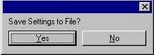
receiver. The Save Settings to Receiver uploads the settings
in the Carlson Field dialog to the receiver so that the next time
the receiver is turned on these settings are still set even without
connecting to Carlson Field. Otherwise, Carlson Field must be
connected to the receiver to setup these options.
Send Command to Receiver allows experienced users to type in
commands using Ashtech GPS receiver commands to set or report
internal settings. (See the Ashtech operations manuals for a
complete list of Ashtech GPS receiver commands.)
Reset Sensor Memory will reset the receiver memory, reinitialize the communications ports and reset the modem. Saved settings on the receiver will be returned to their default values.
Radio Baud Rate allows you to change Pacific Crest radio baud settings through the receiver. The default baud rate is 9600. (Note: If there are communication problems with either port A or B on the Ashtech ZSurveyor receiver, turn off receiver and turn it back on with both keys depressed to reset receiver to factory defaults.)
For the Z-Extreme, the Configure Internal Radio button allows you to change the radio channel and settings. This function will attempt to establish a connection with the internal radio, reporting an error if it is unable to do so. Otherwise, it will open a dialog which will display the current radio channel as well as the valid range of radio channels. Enter the desired radio channel in the edit box and then click on "Program Radio" to set the changes to the radio. Carlson Field will communicate with the radio for a few seconds, and will then request that you power the receiver down, then turn it on again before continuing. It is very important that this is done, or else Carlson Field will be unable to communicate with the ZExtreme. Also note that if the programming of the radio is canceled for any reason, the receiver will still need to be powered down, then powered up again in order for Carlson Field to be able to communicate with it.
Create Base REF File takes a reading from the GPS receiver and stores this lat/lon to a reference file (.ref) that can be used later in Configure Base Station. The purpose is to allow moving the base station based on the current base setup. In this case, Create Base REF File would be run from the rover receiver while in "fixed" position. Then the base could be moved to this point without having to redo the local coordinate alignment.
Configure Base Station initiates the receiver connected
to Carlson Field to be a base and begin broadcasting its stationary
position and satellite corrections to the rover. (See Configure
Base Station for All GPS Brands at end of this section.)
Topcon GNSS/Javad GPS Setup
Radio Port on the Javad base and rover receiver is usually C. Data Port is always A. When using Pacific Crest radios, Javad recommends the new PDL Pacific Crest radios. These must be set to 38,400 baud rate. Javad also uses Spread Spectrum radios which work at 119,200 baud rate.
Receiver Model selects between Legacy, Odyssey and Regency. Currently the Receiver Model does not affect the Carlson Field interface except to determine the default Antenna Type.
Position Update Rate sets the frequency that the receiver calculates and reports position. The faster rates are an option that must be purchased for the receiver.
Antenna Type chooses between an internal and external GPS antennas. This option applies to receivers with built-in antennas.
The RTK Message Type determines the format of the GPS correction message that is used from the base to the rover.
RTK Calculation Mode chooses between Delay and Extrapolate. The Extrapolate mode is needed for fast Position Update Rates.
Satellite Elevation Cutoff is the cutoff vertical angle above the horizon. Any satellites below this angle will be left out of calculations.
Ambiguity Fixing Parameter (95 - 99.9): controls the confidence level of fixed positions. The default is 99.0. At a lower confidence interval the system solves much faster. If the system incorrectly solves the position, then the position error will be much greater than the reported RMS value.
Power Cycle Receiver is the same as turning the Javad receiver off and then on.
Restore Factory Defaults resets the Javad receiver to factory settings the receiver stops acting as base or rover. The baud rate of Port A will be set to 115,200. Reset this to 9600 by turning the receiver off and then on while holding down the FN button. Watch the REC light go from orange to green to red and then let up the FN button. This method can be used if Carlson Field cannot establish communications at any time.
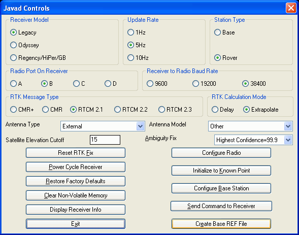
Clear Non-Volatile Memory does everything Restore Factory Defaults does and also wipes out the almanac data that tells it where to look for the satellites. The receiver then downloads a new almanac from the satellites.
Send Command to Receiver allows experienced users to type in commands using Javad GPS receiver commands to set or report internal settings. (See the Javad operations manuals for a complete list of Javad GPS receiver commands.)
Create Base REF File takes a reading from the GPS receiver and stores this lat/lon to a reference file (.ref) that can be used later in Configure Base Station. The purpose is to allow moving the base station based on the current base setup. In this case, Create Base REF File would be run from the rover receiver while in "fixed" position. Then the base could be moved to this point without having to redo the local coordinate alignment.
Configure Base Station initiates the receiver attached to be a base and begin broadcasting its stationary position and satellite corrections to the rover. (See Configure Base Station for All GPS Brands at end of this section.)
Leica GPS Setup
Carlson Field works with the following Leica GPS receivers: System 500, GS50, MC1000 and MK31. The type of Leica receiver is set in the Configure Field command. The options available in the GPS Setup dialog depend on the current type of receiver.
Leica Radio Port is the port on the receiver where the radio is attached, usually 2 or 3. Port 1 is usually the one attached to the computer. For the System 500 receivers, you can also set the radio baud rate, stop bits and parity parameters.


 For the system 500
receivers, you need to specify the antenna types used at both the
base and rover receivers. This antenna type sets the phase center
offsets for the antennas which can affect the reported elevations
by as much as 0.25 foot if not set properly.
For the system 500
receivers, you need to specify the antenna types used at both the
base and rover receivers. This antenna type sets the phase center
offsets for the antennas which can affect the reported elevations
by as much as 0.25 foot if not set properly.
Cell phones can also be used with Leica GPS equipment instead of radios for RTK work.
For GS50 receivers, you can choose between US Coast Guard or Racal for the corrections.
Power Cycle Receiver shuts the receiver off and turns it back on. This forces the receiver to reinitialize tracking satellites and the position solution. This routine is useful if the receiver is stuck in float solution.
Send Command to Receiver allows experienced users to type in Leica commands or send a file to set or report internal settings. (See the Leica operations manuals for a complete list of Leica GPS receiver commands.)
Create Base REF File takes a reading from the GPS receiver and stores this lat/lon to a reference file (.ref) that can be used later in Configure Base Station. The purpose is to allow moving the base station based on the current base setup. In this case, Create Base REF File would be run from the rover receiver while in "fixed" position. Then the base could be moved to this point without having to redo the local coordinate alignment.
Configure Rover sets the receiver to rover mode.
Configure Base Station initiates the receiver attached to be a base and begin broadcasting its stationary position and satellite corrections to the rover. (See Configure Base Station for All GPS Brands at end of this section.)

 Navcom
GPS Setup
Navcom
GPS Setup
 Novatel GPS Setup
Carlson Field works with the original Novatel Outriders and the
just released Outrider DL's including the centimeter accurate RT-2
RTK receivers and the sub-meter accurate Gismo USCG/satellite
RTCM/DGPS beacon receivers.
Radio Port for external radio connection is typically COM 2 on the receiver. The Data Port connected to Carlson Field is typically COM 1.
Differential Mode toggles the Novatel GPS receiver to use RTCA, RTCM or CMR message types. RTCA is proprietary to Novatel and is used only for centimeter accuracy RTK GPS surveying. RTCM can be used with USCG/DGPS beacon signals for sub-meter accuracy. Novatel receivers work with Trimble CMR proprietary message signal type and can be either a base or rover working with Trimble RTK GPS receivers.
Dynamics toggles the rover between Kinematic or Static. The base is always in Kinematic mode. Kinematic is used for surveying while walking with the receiver. Static is for stationary use only at the rover and gives better accuracies. Since Static mode is for more precise measurements, it can be used for GPS alignment points and for any control points. The receiver should not be moved while in Static mode.
Elevation Cutoff is the vertical cut-off angle above the horizon. Any satellites below this limit will be ignored in calculations. 15 is a common setting.
Elevation Type chooses between Mean Sea Level or Ellipsoid for the elevation model used by the receiver.
Solution Reset (Soft Reboot) resets the Novatel receiver in a few seconds. This is used when the rover receiver is locked up or not properly reporting its position in the Monitor function.
Receiver Reset (Full Initialize) essentially does a
factory reset and a power off and on cycle.

A Receiver Reset (Full Initialize) takes three to five minutes to get back on line and become fixed after a full initialize.
Set Radio Channel allows you to change Pacific Crest radio channels through the receiver. The base and rover must operate using the same radio channel.
Send Command to Receiver allows experienced users to type in commands using Novatel GPS receiver commands to set or report internal settings. (See the Novatel operations manuals for a complete list of Novatel GPS receiver commands.)
Check Communication Status checks the radio port operation and reports the status as working or not communicating.
Configure Base Station initiates the receiver connected to be a base and begin broadcasting its stationary position and satellite corrections to the rover. (See Configure Base Station for All GPS Brands at end of this section.)
Sokkia Radian GPS Setup
Radio Port for external radio connection is typically COM 2 on the receiver. The Data Port connected to Carlson Field is typically COM 1.
Differential Mode toggles the Sokkia GPS receiver to use RTCA, RTCM or CMR message types. RTCA is proprietary to Sokkia and is used only for centimeter accuracy RTK GPS surveying. RTCM can be used with USCG/DGPS beacon signals for sub-meter accuracy. Sokkia receivers work with Trimble CMR proprietary message signal type and can be either a base or rover working with Trimble RTK GPS receivers.


Dynamics toggles the rover between Kinematic or Static. The base is always in Kinematic mode. Kinematic is used for surveying while walking with the receiver. Static is for stationary use only at the rover and gives better accuracies. Since Static mode is for more precise measurements, it can be used for GPS alignment points and for any control points. The receiver should not be moved while in Static mode.
Elevation Cutoff is the vertical cut-off angle above the horizon. Any satellites below this limit will be ignored in calculations. 15 is a common setting.
Solution Reset (Soft Reboot) resets the Novatel receiver in a few seconds. This is used when the rover receiver is locked up or not properly reporting its position in the Monitor function.
Receiver Reset (Full Initialize) essentially does a factory reset and a power off and on cycle. A Receiver Reset (Full Initialize) takes three to five minutes to get back on line and become fixed after a full initialize.
Set Radio Channel allows you to change Pacific Crest radio channels through the receiver. The base and rover must operate using the same radio channel.
Send Command to Receiver allows experienced users to type in commands using Sokkia GPS receiver commands to set or report internal settings. (See the Sokkia operations manuals for a complete list of Sokkia GPS receiver commands.)
Check Communication Status checks the radio port operation and reports the status as working or not communicating.
Configure Base Station initiates the receiver connected to be a base and begin broadcasting its stationary position and satellite corrections to the rover. (See Configure Base Station for All GPS Brands at end of this section.)
Trimble GPS Controls
Carlson Field works with the following Trimble receivers: 4000
series, 4700, 4800, 7400, NT300D, GeoExplorer and Pathfinder. The
type of receiver is set in the Configure Field command. The options
available in the GPS Setup dialog depend on the current type of
receiver.
 For the Pathfinder and GeoExplorer,
the Altitude Measurement Type chooses between using
Ellipsoid or Mean Sea Level as the elevation model in the
receiver.
For the Pathfinder and GeoExplorer,
the Altitude Measurement Type chooses between using
Ellipsoid or Mean Sea Level as the elevation model in the
receiver.

 With the Pathfinder, Carlson Field
will activate the receiver when the first Carlson Field command is
run and the receiver will stay active until Carlson Field is
exited. The reason is that the Pathfinder will turn off as soon as
the COM port is turned off. If you need to make Carlson Field turn
off the receiver, then use the Close Communication With Pathfinder
button.
With the Pathfinder, Carlson Field
will activate the receiver when the first Carlson Field command is
run and the receiver will stay active until Carlson Field is
exited. The reason is that the Pathfinder will turn off as soon as
the COM port is turned off. If you need to make Carlson Field turn
off the receiver, then use the Close Communication With Pathfinder
button.
With the Pathfinder, DGPS Correction Source selects
whether the Pathfinder will get its Corrections from a local Coast
Guard Radio Beacon or from the Racal Satellite Correction service.
Note that the Racal option must be enabled on the receiver in order
to use Racal satellite corrections. (See your dealer for details as
to how to do so). If Racal Service is selected as the
correction source, the Racal Region selection will be
enabled. The region corresponding to the relative location of the
receiver should be selected to ensure proper reception of
corrections.

The Pathfinder and 4700/4800 also feature the ability to select a Satellite Elevation Cutoff . All satellites with elevations below this setting will not be used in the final position calculations, even if they are otherwise visible to the receiver.
For 4700/4800 series receivers, the Receiver Type option
must be set to the correct model in order for Carlson Field to
communicate with the receiver. RTK Correction Type selects
what format of RTK corrections between the Base and Rover
receivers. CMR and RTCM formats are available. Radio Baud
Rate should be set to the same setting as the communication
port of the radio connected to the receiver. 4800 bps, 9600 bps,
19,200 bps and 38,400 bps rates are supported. Configure Base
Station will configure the receiver as a base and begin
transmitting corrections via the radio.

Library Drivers - GPS
For library drivers, unlike the legacy Carlson Field GPS drivers,
you select a Base or Rover driver from the Configure Field command
(instead of inside the Equipment Setup dialog). A GPS Base
Equipment Setup dialog is shown below.
General receiver options are configured under the Receiver section. There are
input boxes for Antenna
Height and Elevation
Mask. The antenna height is the rod height of the GPS
receiver. The elevation mask is specified in whole degrees
(above the horizon, or 0 degrees). The Position Rate specifies the rate at
which the GPS receiver will output positions or corrections.
The available position rates vary from receiver to
receiver.
The RTK section is used
to setup the RTK configuration. First, select the
RTK Device to be used, and
click the Configure button
next to it if you need to configure the radio (ie. channels,
etc). Next, select the RTK
Network (if applicable). If available, select the
correct RTK Port and
RTK Baud to define the
connection between the receiver and the RTK device. Then,
select the desired Message
Type (correction type). Finally, enter a Base ID, or leave it blank for 'any
base', and continue by. In the example below, the base
receiver will be configured to output CMR corrections ( Message Type) through the Internal Radio (RTK Device). The RTK Port and RTK Baud are grayed out because these
are known values when using the internal radio on the Altus
APS-3. RTK Network
is not available in the example because it doesn't apply to the
chosen RTK device. The Rover would be configured similarly to
accept CMR corrections on it's internal radio.

To switch to the Rover, you must return to Configure Field >
Equipment Type > Library Drivers and select the GPS Rover
Manufacturer and Model. Similar to configuring a Base,
general receiver options are configured under the Receiver section. In the example
below, the rover receiver will be configured to receive
CMR+ corrections from the
KYTG NTRIP base over an internet connection using
the receiver's Internal
GSM modem (PLEASE NOTE: This is a separate example from
configuring a GPS Base. The examples are not intended to show
how to configure the same Base/Rover pair to work in a differential
configuration, but are intended to show two entirely different
types of configurations.). The RTK Port and RTK Baud are grayed out because these
are known values when using the internal GSM modem on the Altus
APS-3. The Message
Type is grayed out because this is the only message type
available from the KYTG NTRIP base. Also, in the example
below, the user would be required to click the Connect button before exiting the
Rover setup to actually connect to the NTRIP base and start
receiving corrections.
 Normally, the
Configure button next to
the RTK Network is grayed
out, and the Configure
button in the RTK Base
section is used to configure any details about the Base that the
Rover is receiving corrections from. However, NTRIP is slightly different.
When using NTRIP as the
RTK Network the
Configure button next to
the RTK Network is used to configure the NTRIP Broadcaster.
The NTRIP Broadcaster is the server that actually broadcasts it's
available NTRIP bases and their information. Save and Exit will connect to the
displayed NTRIP Broadcaster and download the base list.
Exit will keep the
broadcaster you have selected, but will attempt to load the base
list from memory and will not attempt to connect to the broadcaster
to download the base list.
Normally, the
Configure button next to
the RTK Network is grayed
out, and the Configure
button in the RTK Base
section is used to configure any details about the Base that the
Rover is receiving corrections from. However, NTRIP is slightly different.
When using NTRIP as the
RTK Network the
Configure button next to
the RTK Network is used to configure the NTRIP Broadcaster.
The NTRIP Broadcaster is the server that actually broadcasts it's
available NTRIP bases and their information. Save and Exit will connect to the
displayed NTRIP Broadcaster and download the base list.
Exit will keep the
broadcaster you have selected, but will attempt to load the base
list from memory and will not attempt to connect to the broadcaster
to download the base list.

When using an NTRIP RTK Network, the Configure button in the RTK Base section will display NTRIP
Base information to help the user select the best base
choice. As shown below, NTRIP Base information usually
contains a short name (Name), a descriptive name (Identifier), the
NTRIP Base type (Type), available RTK message type (Format), and
approximate NTRIP Base location (Position). The Send Rover Position To Network toggle
is always grayed out, but displays whether or not the selected
NTRIP Base requires the Rover position to be sent back (ex. this is
typically required by virtual base systems). Once the
preferred NTRIP Base is selected, click the Connect button to actually connect to
the base to begin downloading corrections. After a successful
connection is created, exit the Rover Setup dialog using the
OK button. It is
recommended to goto the Monitor/Skyplot routine to verify that the
Rover is receiving corrections. The Rover's status will be
Float or Fixed/Locked if receiving corrections.

Configure Base for All RTK GPS Brands
Within Equipment Setup, the Configure Base Station button is the command that starts the base receiver broadcasting GPS corrections to the rover. You must click the Configure Base Station button in Equipment Setup while your are connected to the base receiver. The base needs a set of coordinates to use as its stationary position. There are five methods to set the stationary base position: Read from GPS, Enter Lat/Lon, Enter State Plane Coord, and Read From Reference File and Read From Alignment File.
Read from GPS - This method takes one GPS reading from
the base receivers autonomous position and uses it as its "true"
position. The autonomous position can be off of the actual position
by 200 feet. The base will calculate corrections based on this
autonomous position. If you set up the base with this method, the
rovers must be aligned since the corrections they are using
are based on a "true" position that is not really true.
Enter Lat/Lon - requires you to enter the latitude and longitude for the position of the base antenna. This is useful if you are setting up over a USGS monument whose lat/lon you know. It can also be used over a control point whose position is known from GPS post-processing.
Enter State Plane Coord - requires you to enter the State Plane northing and easting for the point that the base is occupying. This is useful if you are setting up over a USGS monument whose coordinates you know.
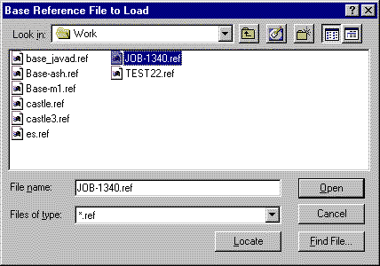
Read From Reference File - reads a previously saved base position file. All of the other methods of setting up the base let you save the base position at the end of setup. If you return to a site, set up the base in exactly the same position, use Read From Reference File to use the same base position and you don't have to re-align the rover: the old alignment is still valid.
Read From Alignment File - reads a position file from one
of the control points in an alignment file. This allows you to
setup the base on one of the control points from the alignment.
Then you don't have to re-align the rover: the old alignment is
still valid.

Method 1 - Read from GPS
Step 1


Method 2 - Enter Lat/Lon
Step 1


Saving Base Settings to a File
It is always recommended to save the base position to a file if you are going to return to the same site survey again. You can setup on the same base position, recall the base REF file and enter the new antenna height. Then you can use the alignment file from the first day in the rover and not have to re-align.
When you save the base antenna position to a file it is stored with a REF extension denoting base reference file. By default, it goes in the Data directory. Input reference filename and pick Save and OK.
Configuring the Rover
After the base is configured, unplug the base receiver from the Carlson Field computer and plug in the rover receiver. In Equipment Setup, toggle the Station Type from Base to Rover. Then pick Exit. This will configure the receiver as a rover.
From the Field drop-down, pick the command Monitor GPS Position. The Status is reported as either Autonomous, Float or Fixed.
If the rover is Autonomous, it is not getting any corrections from the base.
If the status is Float, the rover is receiving corrections, but
has not found the fixed solution. Once the solution becomes Fixed,
the rover is locked on to the base corrections and is calculating
an accurate position.

