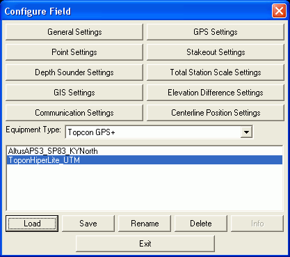
This command sets the equipment type, communication parameters
and other Carlson Field options. Make sure the Equipment
Type box shows the correct GPS or Total Station equipment that
you'll be using. The down triangle button to the right of this box
brings up a list of the equipment types to choose from. There are
ten Settings buttons to
bring up the dialog boxes which are used to change Carlson Field's
default settings. Explanations for each are shown below.
General Settings
If you are using a total station, Rod Height is the distance from the prism to the ground. For GPS, Rod Height is the distance from the center of the GPS antenna to the ground.
The Show Carlson Field Startup Icon controls whether the Carlson Field Startup Icon is displayed in the lower right of the screen. This startup icon brings up the Carlson Field function menu for launching Carlson Field commands without having to pick them from the pull-down menu.
The Twist Screen In Direction Of Movement will rotate the
drawing view so that your current direction of movement is facing
straight up in the view. This rotate is for the view only and does
not change the coordinates. This option only applies to GPS and
robotic total stations in commands that show the arrow icon such as
Track Position.
The Display Feet and Inches
for Total Stations will use a feet and inches display format
(1'2 3/4") in most routines when using a total station.
The Adjust Dialog Font Size
For Resolution will attempt to adjust some dialogs to better
fit the resolution you are using.
The Use Bold Font toggles between using standard or bold font for the Carlson Field dialogs.
The Station Type chooses the format of centerline station labels. Typically 1+00 is used for feet units, 1+000 is used for metric and 100 has no plus symbol in the number.

GPS Settings
The RMS Tolerance checks the RMS values when reading GPS positions. The RMS is the accuracy value reported by the GPS receiver. There are separate settings for the horizontal and vertical RMS values. The RMS (root mean square) value means that the reported coordinate is within +/- the RMS value of the true coordinate to a certain confidence level. The confidence level depends on the GPS receiver. Typically it is a 98% confidence. If either RMS value exceeds the user-defined tolerance while storing points, Carlson Field will default to "No" when it asks if you want to store the point. You are required to choose yes to override the tolerance check and store the point.
Suggestion: When GPS RTK systems loose lock and go "Float", both the horizontal and vertical RMS values typically jump up to sub-meter (1' or higher) values. In Carlson Field, one foot is the default for the GPS RMS Tolerance . Some operators set the GPS RMS Tolerance low to 0.2 to check for high RMS values while still "Fixed".
Store Locked Only - The position of the GPS rover is considered either "Autonomous", "Float" or "Fixed" based on the solution status from the GPS base corrections. When you are storing points and the Store Locked Only box is checked, Carlson Field will only store points if your position is "Fixed". We suggest you leave this box checked. It ensures that you do not record inaccurate points.

Suggestion: When walking in light to heavy canopy, the rover might remain "Float" and display RMS accuracies of over a foot, sub-meter or more. Setting your GPS RMS Tolerance high and turning off Store Fixed Only will allow storing wetland and LOD (limits of disturbance) points under canopy that require only sub-meter tolerances. (USCG beacon DGPS sub-meter RTK GPS will always use these settings.)
Projection Type - defines the datum coordinate system to be used for converting the latitude/longitude from the GPS receiver into cartesian coordinates. For the United States two separate horizontal control systems have been developed by the Federal Government: State Plane 1927 and State Plane 1983. For international use the UTM (Universal Transverse and Mercator System) should be selected. The Lat/Lon option will convert the latitude/longitude from degrees minutes seconds format into decimal degrees. This option is useful when working in a decimal degrees lat/lon coordinate system.
Zone - For State Plane projections, you must select the correct state zone that you are working in. For UTM, the Automatic Zone option will have the program automatically use the correct UTM zone for your location. Otherwise for UTM, you can manually set a specific UTM zone. This manual option applies to working on the border between zones and you want to force the program to always use one of those zones.
Important: Coordinates of surveyed points will be inaccurate if the Projection Type and Zone settings are wrong. If you have done survey work and then realize that they are set wrong, then your point coordinates are wrong, but your work is not wasted. Carlson Field records the latitude, longitude and height of every point in a *.RW5 file. You can input the correct projection zone settings later and reprocess your data using the Edit-Process Raw File command.
Model - For UTM, this option sets the ellipsoid constants for converting the lat/lon to UTM coordinates. The following is a list of the models:
Model Earth Radius(m) Flattening factorTransformation - The transformation in the Align Local Coordinates command can either be by plane similarity or rigid body methods. Both methods use a best-fit least squares transformation. The difference is that the rigid body method does a transformation with a translation and rotation and without a scale. The plane similarity does a rotation, translation and scale. This option only applies when two or more points are used in Align Local Coordinates.
One Pt Align Azimuth - This option applies to the rotation when using one point in Align Local Coordinates. For this alignment method, the state plane coordinate is translated to the local coordinate. Then the rotation can use either the state plane grid or the geodetic as north. No scale is applied in this transformation. The state plane and geodetic true north diverge slightly in the east and west edges of the state plane zone. This option allows you to choose which north to use.
Two Point Align Method - This option applies only two point alignments. Possible values are Fit & Rotate and Rotate Only. Fit & Rotate (the default) will use the second alignment point for rotation, translation, and scale (depending on the value set for Transformation). The Rotate Only option will use the second point of a two point alignment for rotation only.
Geoid To Apply - This option will account for the geoid undulation in determining the orthometric elevation of the measurement. The definition of the geoid model as currently adopted by the National Geodetic Survey is the equipotential surface of the Earth's gravity field which best fits, in a least squares sense, global mean sea level. Orthometric elevation measurements are used in survey calculations. In order to convert ellipsoid heights (He) as measured by GPS into orthometric elevations (Eo), you must provide for a correction between the GPS-measured ellipsoid (reference ellipsoid) and a constant level gravitational surface, the geoid. This correction is the geoid undulation (Ug). The formula is He=Eo + Ug.
The Geoid models are essentially large elevation difference models in grid format. Carlson Field has two geoid models available. Geoid99 covers the United States at 1 minute grid intervals. EGM96 covers the entire globe at 15 minute intervals. These Geoid models are huge and take a lot of disk space and memory. The Geoid model files are not installed automatically and instead need to be installed by going to the Geoid folder on the Carlson Field installation CD. Once installed onto Carlson Field, you then need to specify your location by lat/lon so that the program only needs to load a local portion of the Geoid model. To set your local Geoid area, pick the Set Geoid Area button. Setting the Geoid area will carve out a Geoid model around the specified lat/lon covering a square area of 2 degrees by 2 degrees which is about 100 miles by 100 miles.
Carlson Field applies the Geoid model by subtracting the Geoid
undulation from the GPS elevation.
The resulting elevation is then used and displayed. In the Monitor
function, the Geoid undulation is displayed.
In practice, the Geoid model is most applicable to two types of alignment scenarios. One of these types is when setting up the base over a known point and having no alignment control points. The other is when there is one alignment control point. When using multiple alignment control points, the Geoid model is not as important because Carlson Field can model the elevation difference which can generally pick up the local Geoid undulation.
Project Scale Factor - After converting the LAT/LONG from
the GPS to the state plane coordinates and applying the Align Local
Coordinates, the Project Scale Factor is applied as the final
adjustment to the coordinates. This adjustment is used on the X,Y
and not the Z. The Project Scale Factor is applied by dividing the
distance between the coordinate and a base point by the Project
Scale Factor. The coordinate is then set by starting from the base
point and moving in the direction to the coordinate for the
adjusted distance. The base point is the first point in Align Local
Coordinates. If there are no points specified in Align Local
Coordinates, then 0,0 is used as base point. The Project Scale
Factor can be entered directly or calculated using the grid factor
and elevation for the current position. When using the current
position, the program will read the LAT/LONG from the GPS receiver.
The scale factor is then calculated as: (State Plane Grid Factor -
(Elevation/Earth Radius)).
Default Alignment -
This option sets the alignment file to use by default for new
drawings. This feature applies when you will keep working at the
same site with the same base receiver setup.
Helmert 7-Parameter Transformation - These settings apply
when the Transformation is set to Helmert. The Helmert 7-parameters
can either be calculated by the program using the control points in
the localization or user-entered.
Laser Offset Settings - There is an option to use a laser for
reading the distance and angle for offset points. When this option
is enabled, you can choose the laser equipment type and
communication parameters. The serial port for the laser must be
different than the GPS which requires at least two serial ports on
the computer. When using a laser for offsets, the program will read
the current position from the GPS and then read the laser for the
distance and angle to the point. This combination allows you to
calculate points that cannot be directly reached by the GPS. There
are two methods in the Point Store command to use the laser when
this option is enabled. The Point Store dialog will have a new
Laser button which will bring up another dialog that allows you to
take multiple shots from the laser. The other method is to click on
the Offset toggle in the Point Store dialog. Then when you do the
Read function, the program will read the GPS position and then
pop-up a dialog for taking one offset shot.
Point Settings
Beep for Store Point - This option will make a
triple beep to indicate when a point is stored in the coordinate
file.
User-Entered Point Notes - Point Notes are additional
descriptions that can be stored with a point. A regular point
consists of a point number, northing, easting, elevation and 32
character description. These points are stored in a .CRD file.
Point Notes are a way to add an unlimited number of lines of text
to a point number. With Point Notes ON in the Store Point command,
the program will prompt for notes after collecting a point. The
notes are stored in a file that uses the name of the coordinate
file with a .NOT extension. For example, a coordinate file called
JOB5.CRD would have a note file called JOB5.NOT.

Coordinates in Point Notes - When storing a point, this option will store the point number, northing, easting, elevation and description in the point notes as well. This may be used as a backup or reference to coordinate data as it was originally stored.
GPS RMS in Point Notes - When storing a point, this option will store the horizontal and vertical RMS values in the note field for the point. This offers a good check on the quality of the shot.
GPS DOPs in Point Notes - When storing a point, this option will store the DOP (dilution of precision) values as reported from the GPS receiver.
Rod Height in Point Notes - When storing a point, this option will store the rod height value in the note field for the point.
Project Scaler in Point Notes - When storing a point, this option will store the project scale factor in the note field for the point.
Time/Date in Point Notes - This option will store the
time and date that the point was stored in the note file. Carlson
Field will read the time from the computer.
Drawing Options control how points are drawn by default. It
controls the layer, symbol number and whether points will be drawn
with descriptions and elevations. Carlson Field's Field to Finish
code table can override these defaults.
The symbol used for default points is displayed. You can choose another symbol by changing the Symbol name or by selecting one from the table that the Select Symbol button brings up. Default point settings are used for points whose descriptions don't correspond to any category on the Field to Finish code table.
Label Descriptions and Label Elevations Control whether these two items of information appear on your drawing next to each point.
Locate on Real Z Axis will record points with their true elevations. If this setting is off, all points recorded will have an elevation of zero.
Layer for Points indicates the layer where all default points will be drawn. For points using a code on the code table, the code table will determine their layer.
Number of Readings specifies how many times Carlson Field will read from the instrument in the Read function of the Point Store command. This applies to both GPS and total stations. The readings will be averaged to find a more accurate position.
Direct-Reverse Tolerances are used with total stations to check the pairs of direct and reverse horizontal angles, vertical angles and distances. When these values are off by more than the tolerance, the program will display a warning.
Field to Finish is explained fully in the Field to Finish command definition. Basically it uses a code table which holds information on types of points (ie. Man Hole or Edge of Pavement). When the settings Use Code Table is selected, Carlson Field will look to the code table for how to draw points of a particular code description.
The file containing the active code table appears after Code File: You can change this with the button Select File.
The Split Multiple Codes option will draw multiple points from the same point when that point description has multiple codes. For example, a point with description "EP DR" will draw the point twice: once with the properties of code EP and a second time using code DR. When this option is off, the program will use the first code and draw the point once.
The Check Descriptions With Code Table option will display a warning before storing a point if that point description is not found in the code table. With this option off, the program will go ahead and store the point and the point will be drawn using the default point properties.
Stakeout Settings
Display GPS RMS in Stakeout causes Carlson Field to report
the constantly updating horizontal RMS accuracy values while
staking a point. The only disadvantage to having this option active
is that it slows down a little the stakeout position update.
Draw Trail displays a line in the stakeout screen showing
where you've been as you move towards the stakeout point. This
option only applies to GPS.
Prompt For Snap On Screen
Pick controls whether you are prompted to select an object
snap when picking points from the screen during stakeout.
Auto Zoom will zoom the drawing display in or out so that both your current position and stakeout target are visible on the screen.
Zero Horizontal Angle To Target will set the horizontal
angle of the total station to zero in the direction towards the
stakeout point. When stakeout is completed, the horizontal angle is
set back to the original value. This option only applies to total
stations.
Automatic Turn To Point Type
For Robotic Total Stations does two things. First, it
controls whether or not stakeout automatically turns to the
stakeout point. Second, it allows the user to select what
type of turn is performed: Horizontal Angle only, or Horizontal and
Vertical Angle.
Default Stakeout Mode
allows the user to select a default stakeout mode to be used when
entering the stakeout routine. Choices include the stakeout
modes: Station-Offset, Point Number, and Pick Point. If Pick
Point is selected as the default stakeout mode, the user can also
define the default object snaps.
Store Cutsheet/Stakeout Data in Note File will store stakeout data in the note file (.NOT) for the current coordinate file. At the end of staking out a point, there is an option to store the staked coordinates in the current coordinate file. This stakeout note file option allows you to store more stakeout data in addition to the staked coordinates. This additional data includes the target coordinates and horizontal and vertical difference between the staked and target points. This stakeout note data can be used in reports with the List Points or CutSheet Report commands.
Store Cutsheet/Stakeout Data in Excel Spreadsheet will display a cutsheet report in an Excel spreadsheet. The spreadsheet will pop-up at the end of each point stakeout. The report can be saved in Excel format and processed by Excel.
Store Stakeout Points To Separate Coordinate File will store the staked points to a different coordinate file besides the current coordinate file. This allows you to use the same point number for the target and staked points. The staked point coordinate file can be specified by picking the Select Coordinate File button.
Check Total Station Turn Angle will compare the angle from the instrument and the angle to the target point. If this difference is greater than the specified tolerance, then Carlson Field will display a warning message.
Stakeout Tolerance controls the maximum difference between the target location and actual staked point. When the staked point is beyond the tolerance, Carlson Field displays a warning dialog.

GPS Number of Reads for Final Average specifies how many times Carlson Field will read the GPS receiver position for the final staked point. These reading are averaged. Averaging several readings while occupying one point yields a more accurate result, but inevitably takes longer.
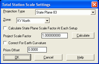
Total Station Scale Settings
These settings apply only to total stations. The Project Scale Factor is multiplied by the measured distance from the total station when calculating the foresight point coordinates. A typical project scale factor for working in state plane coordinates is slightly less than one. Factors greater than 2.0 or less than 0.5 are not allowed. The Project Scale Factor can be entered directly or choose the Calculate button. The Calculate function takes a state plane coordinate and calculates the project scale factor as the state plane grid factor minus the elevation factor (Grid Factor - elevation/earth radius). The state plane coordinate is specified by a point number from the current coordinate file.
The Calculate State Plane Scale Factor At Each Setup option will calculate the scale factor for each shot as the combined grid and elevation factors (see above equation). The scale factor is calculated at both the occupied and foresight points and then averaged. To use this option, you must be working in state plane coordinates and set the state plane zone in this dialog.
The Correct For Earth Curvature option adjusts the
horizontal distance and vertical difference to the foresight point
to account for the earth curvature.
Prism Offset is for use
with total stations to account for the offset (in mm) of the prism
in use. It is recommended to keep this at zero, and set the
prism offset in the instrument.
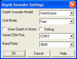
Depth Sounder Settings
Carlson Field can use depth sounders in combination with GPS to
collect points of underwater surfaces. Carlson Field supports depth
sounders that output standard NMEA data. There are several
models to choose from: Hydrotrac, Horizon, Odom Digitrace,
InnerSpace, and Generic. For the Odom Digitrace and InnerSpace
models, you also need to specify the depth unit mode that the
instrument is set to.
The Store Depth In Notes option will record the water
depth in the current note file (.NOT) when a point is stored to the
coordinate file.
The Debug toggle can be used when contacting technical support to diagnose communications issues between the depth sounder and Carlson Field.
The depth sounder must be connected to a separate serial port
than the GPS. The Baud Rate between the computer serial port
and the depth sounder is also specified here.
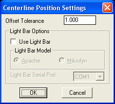
Elevation Difference Settings
These setting apply to the Elevation Difference command. Grading
Tolerance is the target difference between the actual elevation and
the design surface. Carlson Field can use an external Light Bar to
indicate whether your current position is in cut, fill or on-grade.
Currently Carlson Field supports light bars made by Apache and
Mikrofyn. The Light Bar must be connected to a separate serial port
than the GPS.

GIS Settings
A standard point is stored in the coordinate file with a maximum 32 character description. The GIS Settings allow you to store more data with each point.
The Store Data In Note File option will record additional fields for each point in the note file. The note file has the same name as the current coordinate file except with a .NOT instead of .CRD file extension. The fields that are recorded are defined by the GIS File (.GIS). This file defines a sequence of field names and prompts. For example, a GIS file for manholes could contain Location, Depth and Condition fields. Choose the Select File button to choose the GIS file to use. Or use the Select GIS File Automatically by Point Description to use different GIS files depending on the point description. With this option, the program will look for a GIS file with the same name as the point description. For example, if the point description is MH, then the GIS file will be MH.GIS. See the Define Note File Prompts command for more information.
The Store Data Direct To Database option will store additional fields for each point in a Microsoft Access database. The database to store the data is set in the Output File line. The Template File is a database that defines the fields to record. See the Define Template Database command for more information.

Centerline Position Settings
Similar to Elevation Difference Settings only for the Centerline Position command.
Communication Port Settings
Serial COM Port - The GPS receiver or total station
attaches to your Carlson Field computer using a serial cable. This
cable is plugged into a serial COM port on your computer called 1,
2, 3 or 4 . Check the circle denoting the COM Port to be
used.
The Baud Rate, Parity, Char Length and Stop Bits are the serial port communication parameters for the Carlson Field computer. These parameters need to match the parameters on the instrument that you are using. The Defaults button will set these communication parameters to the standard parameters for the current equipment type.

Equipment Type
The Equipment Type droplist allows the user to select the instrument driver to use. The very last entry is for "Library Drivers" which are instrument drivers that follow a new Carlson architecture and support many advanced features (ex. NTRIP). These "Library Drivers" are different from the legacy Carlson Field instrument drivers; they are shared with other Carlson products (ie. SurvCE and Carlson Grade). To select a "Library Driver", select that item and press the Edit button. Please note, that the Edit button is only active for "Library Drivers".
 Selection of a "Library
Driver" is split into two types: Base and Rover. After selecting the
Driver Type, select the
proper manufacturer and model to match the equipment being
used.
Selection of a "Library
Driver" is split into two types: Base and Rover. After selecting the
Driver Type, select the
proper manufacturer and model to match the equipment being
used.
 Carlson Field also allows the user to
save and recall equipment configurations. If you use the same
equipment in different configurations, saving the configuration is
an easy way to recall it later without missing a setting.
First, select the Equipment
Type you wish to save a configuration for. Next, make
sure all the instrument settings are as desired by running through
Equipment Setup.
Finally, press the Save
button and enter a description configuration name that will help
remind you what the configuration is used for. Keep in mind,
saving a configuration will also save the current GPS Settings (ie. projection type,
etc).
Carlson Field also allows the user to
save and recall equipment configurations. If you use the same
equipment in different configurations, saving the configuration is
an easy way to recall it later without missing a setting.
First, select the Equipment
Type you wish to save a configuration for. Next, make
sure all the instrument settings are as desired by running through
Equipment Setup.
Finally, press the Save
button and enter a description configuration name that will help
remind you what the configuration is used for. Keep in mind,
saving a configuration will also save the current GPS Settings (ie. projection type,
etc).
To recall a saved configuration, just select the configuration
and press the Load
button.