


 When using a description table, any INTEGER numbers
in the description field of the data coming from the data collector
will be replaced by the description in the table. For example, if
your description is "13 5", the description put in the coordinate
or raw data file will be "CL CMP".
When using a description table, any INTEGER numbers
in the description field of the data coming from the data collector
will be replaced by the description in the table. For example, if
your description is "13 5", the description put in the coordinate
or raw data file will be "CL CMP".

 When you
select the down button to the right of the data collector shown and
the “Show Defaults only” box is unchecked, you will see the
complete list of all the data collectors that C&G interfaces
with.
When you
select the down button to the right of the data collector shown and
the “Show Defaults only” box is unchecked, you will see the
complete list of all the data collectors that C&G interfaces
with. You also can create a Default List, This default list
should consist of the various data collectors your company may have
and/or interface with on a daily basis.
You also can create a Default List, This default list
should consist of the various data collectors your company may have
and/or interface with on a daily basis.  To add a
data collector to the default data collector
list:
To add a
data collector to the default data collector
list:
 First make
sure the Show Defaults only box is unchecked. Next Select a data
collector from the list by scrolling up and down the list using the
arrow keys. When the new data collector is selected, make sure the
communication parameters are correct to the data collector. Once
the settings are correct, click Add DC button Now click the Save
List to save the changes to the list.
First make
sure the Show Defaults only box is unchecked. Next Select a data
collector from the list by scrolling up and down the list using the
arrow keys. When the new data collector is selected, make sure the
communication parameters are correct to the data collector. Once
the settings are correct, click Add DC button Now click the Save
List to save the changes to the list.

 As mentioned earlier you can have multiple
description tables, here is where you would select the description
table to use.
As mentioned earlier you can have multiple
description tables, here is where you would select the description
table to use.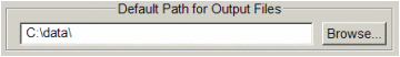 Allows
you to set the default location for storing transferred files
Allows
you to set the default location for storing transferred files You will have the following options:
 Change file
select from: Click the file button to select the coordinate
file that you want transfer coordinates from.
Change file
select from: Click the file button to select the coordinate
file that you want transfer coordinates from. Choose Points: This option allows you
to select groups of points to be included from the file you have
opened, using the C&G selection options.
Choose Points: This option allows you
to select groups of points to be included from the file you have
opened, using the C&G selection options. Block: select blocks of
Points.
Block: select blocks of
Points. Desc:
select points by their description.
Desc:
select points by their description.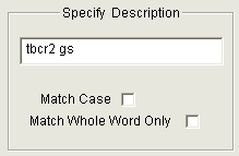 Match Case: Case sensitive compare.
 Low
Value:
Low
Value: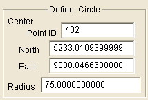 If a
point number is entered in the point ID box, the northing and
easting of that point will be used for the center of the search
circle. To manually enter a northing and easting, leave the Point
ID box empty and enter the values for the northing and easting of
the circle. Enter the radius for the search circle.
If a
point number is entered in the point ID box, the northing and
easting of that point will be used for the center of the search
circle. To manually enter a northing and easting, leave the Point
ID box empty and enter the values for the northing and easting of
the circle. Enter the radius for the search circle. If
a point number is entered in the point ID box, the northing and
easting of that point will be used for that corner of the
rectangle. To manually enter a northing and easting, leave the
Point ID box empty and the northing and easting values. The two
points defined the diagonal corners of the rectangle.
If
a point number is entered in the point ID box, the northing and
easting of that point will be used for that corner of the
rectangle. To manually enter a northing and easting, leave the
Point ID box empty and the northing and easting values. The two
points defined the diagonal corners of the rectangle.
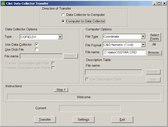
 There
three different dialog boxes involved with data collection
transfer:
There
three different dialog boxes involved with data collection
transfer:
 On the desk top data collection transfer dialog box,
set the following:
On the desk top data collection transfer dialog box,
set the following:


 Select the File you wish to download:
and press OK.
Select the File you wish to download:
and press OK.
 You have the following choices:
 Check Settings to make
sure all options are set correctly
Check Settings to make
sure all options are set correctly Note: See opening section of this
chapter for detailed instructions on the Settings dialog box and on
sending and receiving files.
Note: See opening section of this
chapter for detailed instructions on the Settings dialog box and on
sending and receiving files.
 Use the interface cable supplied with the CR2 unit
and plug it into the comm port on the computer. Make sure you
select the Topcon CR2 data collector and the correct comm port.
Use the interface cable supplied with the CR2 unit
and plug it into the comm port on the computer. Make sure you
select the Topcon CR2 data collector and the correct comm port. Note: See
opening section of this chapter for detailed instructions on the
settings dialog box and on sending and receiving files.
Note: See
opening section of this chapter for detailed instructions on the
settings dialog box and on sending and receiving files. Select the Wild: GIF-2 under Equipment
Options. Before transferring data from the GRE3/4 to your computer,
you must first set up the transfer parameters in the GRE3. To do
this follow these steps on the GRE3/4:
Select the Wild: GIF-2 under Equipment
Options. Before transferring data from the GRE3/4 to your computer,
you must first set up the transfer parameters in the GRE3. To do
this follow these steps on the GRE3/4: This Option actually reads and displays the data
files on the GEODAT 500 data collector. From the display options
you can select to view all files, just coordinate files or just raw
files.
This Option actually reads and displays the data
files on the GEODAT 500 data collector. From the display options
you can select to view all files, just coordinate files or just raw
files. The
Geodat 500 program allows:
The
Geodat 500 program allows: Select the Receive raw data option on the
computer. On the SMI, select TOPC and then RAW. The transfer will
begin. The file name will be shown on the screen after the transfer
is complete. You may enter a new file name if you wish. Our
reduction program does not allow a raw data file with mixed angle
types (for example: azimuths, angles right, deflections, etc.).
When you are collecting data on the SMI, stick to one angle type.
You can mix distance types if you wish (slope/zenith,
horizontal/vertical).
Select the Receive raw data option on the
computer. On the SMI, select TOPC and then RAW. The transfer will
begin. The file name will be shown on the screen after the transfer
is complete. You may enter a new file name if you wish. Our
reduction program does not allow a raw data file with mixed angle
types (for example: azimuths, angles right, deflections, etc.).
When you are collecting data on the SMI, stick to one angle type.
You can mix distance types if you wish (slope/zenith,
horizontal/vertical).

