CGEditor
The CGEditor is an integral part of preparing files for use for
C&G applications. The CGEditor is a very powerful
tool. You can open multiple data files of any supported file
type and edit the files as needed. The CGEditor has a full
complement of tools for searching and replacing and navigating
within a file. It will also allow you to cut or copy records
from one file and paste them into another file in order to merge
files, move data between phases of a job, etc.
Types of data files
supported
The CGEditor can create and/or edit four types of data files used
by CGSurvey and Carlson.
Raw
Data Files
Raw data files contain information
pertaining to a field traverse. Raw data files are typically
downloaded from the data collector and converted to the C&G raw
data file format. These files have the extension .cgr.
Map
Check Files
Map Check files contain bearing,
distance and curve information and are typically used to calculate
the closure of a deed description. These files have the
extension .cgm.
Cross Section Files
Cross Section files contain one or
more cross sections identified by their station along the
alignment. Each cross section record has the percent grade
defined for its left and right slopes. Following the
“Station” record are several “Point” records containing the
elevations and offsets of the points along the cross section.
Cross section files consist of a pair of files; the main data file
has the extension .cew and the index file has the extension
.cex.
Template Files
Template files are merely cross
section files that represent a standard cross section and can be
used to generate other cross section files. However, unlike
cross section files, template files use an integer ID instead of a
station to uniquely identify each template. Like cross
section files, the percent grade is defined for the left and right
slopes of each template and there are a set of “Point” records
specifying the template elevation at a given offset. The
centerline elevation at offset 0.00 is typically set to 0.00.
Template files consist of a pair of files; the main data file has
the extension .ctp and the index file has the extension .ctx.
NOTE: The CGEditor program
sold as part of the standalone
version of SurvNET can only be used to edit raw data
files.
Using the CGEditor
The CGEditor can be used to create new files or edit existing
files. It uses a multi-document interface, so you can edit or
view several files of several different types at the same
time. The following sections will describe how to open and
edit files.
Opening Existing Files
To open an existing file, click on the File menu then choose Open in the submenu. You can then
use the Open file dialog box to browse to the desired file.
Check to make sure the Files of
Type: is set correctly. Click on the desired file to
highlight it, then click the Open button.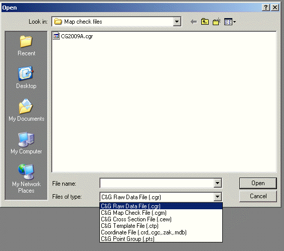
Creating Files
To create a new file, use the File menu and choose New and then click on the type of file
you wish to create: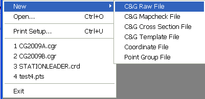
C&G Raw File
C&G Mapcheck
File
C&G Cross Section
File
C&G Template
File
Coordinate File
Point Group File
After clicking the menu item for the type of new file you wish to
create, a temporary file is created with no data in it and a
spreadsheet-like window will open. At this point more menus
items will be added to the main menu and, as you will see, the
Add menu item will allow
you to insert data rows (or records) where you can enter your
data.
NOTE: The CGEditor program
sold as part of the standalone version of SurvNET can only be used
to edit raw data files.
The CGEditor Menus
File Menu
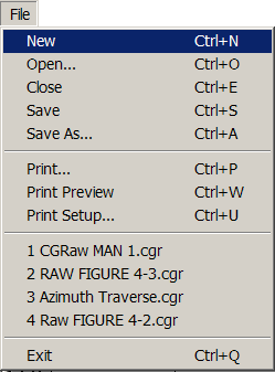 Many of the following File menu items will be
familiar to experienced Windows users:
Many of the following File menu items will be
familiar to experienced Windows users:
New: Allows you to create a
new file.
Open (Ctrl + O): Brings up
the Open File dialog box so you can select and edit an existing
file.
Close (Ctrl + E): Closes
the current data file. If more than one file is open, the file that
is currently being worked on will be closed.
Save (Ctrl + S): Saves the
current file.
Save As: Allows the user to
save the current file to a file having a different name.
Print (Ctrl + P): Allows
the user to print a copy of the currently active file.
Print Preview (Ctrl + W):
Display a preview of the file about to be printed.
Print Setup (Ctrl + u):
Printer selection as well as page size and layout.
Exit (Ctrl + Q): Exit the
CGEditor application.
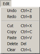
Edit Menu
As with the File menu, the Edit menu is typical of most Windows
programs.
Most of the items in the Edit menu require that either a field
within a record, or the entire record itself, be selected
(highlighted) before clicking the menu item. To select a an
individual data item (or field) in a data record simply click the
field. To select a record (row) simply click in the first
field (Type or Row#) for the desired record.
Undo (Ctrl + Z): Undoes the
most recent editing action. (you need not have anything highlighted
for this item)
Redo (Ctrl + Y): Reverses
the most recent undo action. (you need not have anything
highlighted for this item)
Cut (Ctrl + X): Cuts the
currently highlighted cell or record. You may then use the
paste command to put the cut cell or record in another
location.
Copy (Ctrl + C): Copies the
currently highlighted cell or record. You may then use the
paste command to put the copied cell or record in another
location.
Paste (Ctrl + V): Allows
you to paste any previously cut or copied cell or record to the
currently highlighted location.
If entire records are being pasted and only a field is currently
highlighted, the pasted records will be inserted above the current
record. However, if one or more entire records are currently
highlighted, the pasted records will replace the highlighted
records.
Delete (<Delete>
key): Deletes the currently highlighted field or record.
Select All (Ctrl + A):
Selects all the records in the current data file.
Clear (Ctrl + L): Removes
the data from the selected field or record.
Add Menu
The Add menu allows you to add a record to the current file.
The Add menu item appends the record to the end of the file.
The types of records that can be added will depend on the
type of file being edited, these record types will be described in
more detail in later sections for each type of file you can
editor.
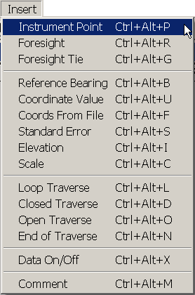
Insert Menu
The Insert menu allows you to insert a record above the current
record.
The types of records that can be inserted will depend on the type
of file being edited, these record types will be described in more
detail in later sections for each type of file you can edit.
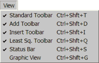
View Menu
The View menu allows you to turn tool bars on or off. The
items listed in the View menu will differ for different types of
files. The individual tool bars will be discussed in the sections
pertaining to the various types of files that can be edited.
Standard Tool Bar
The above figure shows the standard tool bar. The Standard
toolbar is the same for all types of files. It allows you to
create all the various files that can be edited by the
CGEditor. It allows you to open and save files. It
allows you to cut, copy and paste and undo and redo as well as
print the current file.
Settings
The Settings Menu will differ
depending on the type of file being edited. But generally contains
the settings for the file and the record colors.
Tools
The Tools Menu contains a variety of spread sheet tools, such as
find, find next, find and replace etc. The menu will vary
slightly for each type of data file and will be discussed in the
sections pertaining to the various file types.
Windows
This menu contains many of the standard Window menu items found in
other programs. It allows you to arrange the currently open
windows in several configurations. It has the added
functionality of the New Window command which allows you to have
two or more views of a single file.
Editing Traverse Raw Data Files
Traverse types
The raw data file can contain data pertaining to one or more
traverses. If you will be using SurvNET to process the data, there
is no need to delineate separate traverses in the raw data file.
However, if you are using the old C&G traverse reduction
program, and you want to combine more than one traverse in a raw
data file, you will need to use the special traverse code records
at the beginning and end of each traverse.
There are three basic types of traverses:
Closed Loop Traverse
Closed Traverse Beginning and
Ending at Known Points
Open Traverse and Side
Shots
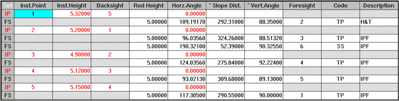
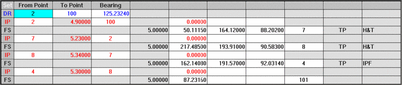
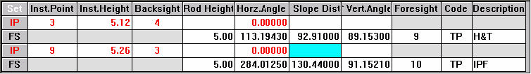
Figures 1, 2, 3 and 4 show illustrations of each of these traverse
types. Below each illustration you will also see the
accompanying raw data as seen in the CGEditor.
Closed Loop
A closed loop begins and ends on the same two points as shown below
in Figure 1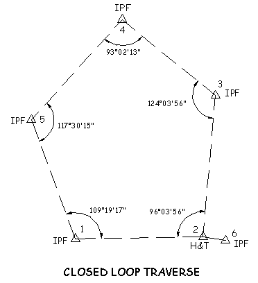 Figure 1
Closed Loop beginning and ending on known points
Figure 2 shows a closed traverse beginning on two known points (1
and 2) and ending on two known points (4 and 5). With this
type of traverse, both a linear and angular closure can be
calculated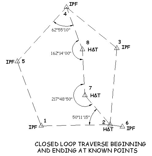 Figure 2
Loop beginning on two known points and closing on an
azimuth
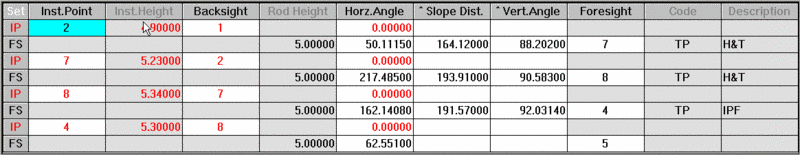
Figure 3 illustrates a traverse that begins on two known points, or
a single known point and a back sight azimuth, and ends on one
known point. In this case it is only possible to calculate a
linear closure. 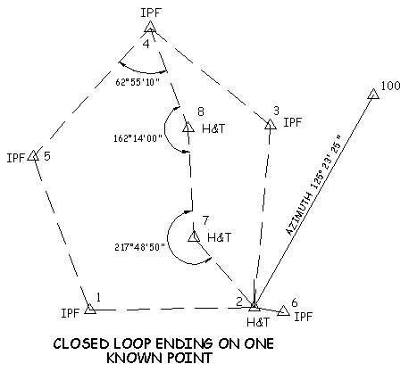 Figure
3
Figure
3
Open Traverse
Figure 4 shows an open traverse (side shots).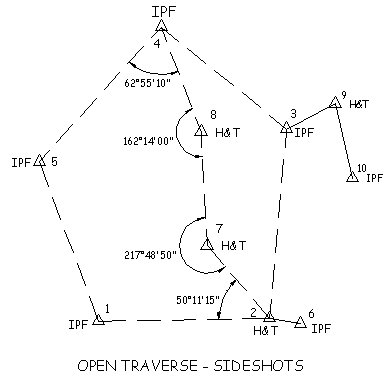 Figure
4
Figure
4
Note: The data shown in the
CGEditor views accompanying the four illustrations include
instrument height (HI) and rod height entries. However,
if you have elevations turned off, these entries are
optional. Also, the examples use single distance and
angle entries but multiple measurements are allowed.
In these figures each traverse has been placed in a separate raw
data file. However, with the use of special codes you
can combine multiple traverses in a single raw data file.
Entering and Editing Traverse Data
In the CGEditor “Raw Data” refers to unadjusted field traverse
data, typically downloaded to the PC from a data collector.
C&G raw data files have the extension .CGR.
Creating or Opening a Raw Data File
To create a new file or open an existing file click on the
File menu then either click
on New or Open. If you click on
New, another submenu will
appear, pick C&G Raw Data
File. In either case you will then see a file
dialog. Browse to the directory where you wish to work and,
if creating a new file, type in a file name, or, if opening an
existing file, click on a raw data file (*.cgr). Next, click
the Save button for a new
file or the Open button for
an existing file.
If you are creating a new file, an empty file will be shown in its
own document window within the editor. If you are editing an
existing file, the data from the file will appear in a similar
document window. It is possible to have multiple documents
open at the same time. So you could create a new file and
open an existing file in the same editing session and each would
appear in its own window in the editor. You can have as many
new and/or existing files open as your project demands.
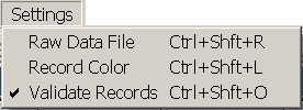
Settings
Before entering any data you should check the current
settings. Click the Settings menu item then click Raw Data
File to review and/or change the current settings. (See
Settings Menu section later in this section.)
Traverse Data Entry
A line or row in the raw data file is referred to as a record and
each item of data in a record is referred to as a field.
There are several types of records that you may use in a raw data
file:
Instrument Point
Foresight
Foresight Tie
Reference Bearing
Coordinate Value
Standard Errors
Control
Measurement
Setup
Elevation
Scale
Loop Traverse
Closed Traverse
Open Traverse
End Traverse
Data on/off
Comment
The type of data required for each of these types of records
varies. Some require no data entry and are only “flags” to
signify the beginning or ending of a series of records, others
require only one field to be filled out, while others require
several fields of data.
Adding and Inserting new records
When creating a new file, to begin entering data you must select
from the Add or
Insert menus to create the
first blank record and begin data entry. Depending on what
type of record you are editing, when you press <Enter> for
the last field in the record, the following record will be added
automatically.
Note: If the Add and/or Insert toolbars are not showing, click
on the View menu then click on the toolbar you want to turn on.
When you click on one of the Add menu items or toolbar icons, an
empty record is added to the end of the file. If you click on
one of the Insert menu
items or toolbar icons, an empty record is inserted above the
currently active record or field. To make a record the
currently active record, just click on one of its fields.
Moving from field to field:
While entering data, to move to the next field, press the Enter or
the Tab key. To move to the preceding field press the Esc key
or both the Shift and Tab keys at the same time.
Insert and Add menus
Instrument Point
records
The first record of a raw data file is often an instrument
point. Add or insert a blank record using the menus or
toolbars. Fill in the following fields in the new instrument
point record:
Inst. Point:
Enter the point ID of the
instrument point.
Inst. Height (or HI):
Enter the instrument height.
This may be either the distance from the IP on the ground
(“Plus-up”) or the actual elevation of the instrument, depending on
how the data is to be reduced. This field will only be active
if elevations are on. (See the Settings section in the
Entering and Editing Traverse Data section of this chapter). If
elevations are ON and you leave this field BLANK (zero is a valid
height), all measurements taken a this setup will be considered 2D
and no elevations will be calculated.
Backsight:
Enter the point ID for the
backsight.
Rod Height:
Enter the rod height. This field
will only be active if elevations are on. (See the Settings
section in the Entering and Editing Traverse Data section of this
chapter).
Horz. Angle:
Enter the
instrument’s initial horizontal angle reading at the
backsight. When doing an azimuth traverse, no entry is
required here.
Note: on doubled angles:
Doubled angles require 2 Instrument Point records. Each new
instrument setup requires a 0 to the back sight. The first
angle to the foresight is the single angle. This angle is locked
into the gun and the back sight is retaken. The second angle
to the foresight is the doubled angle. You may also double
angles to side shots.
Slope Distance and Vertical Angle
or Horizontal Distance and Vertical Distance to the Back
sight:
Enter the appropriate distance
and/or angle. A blank is assumed to be a zero.
Note: When the Slope Dist/Vert Angle or Horz. Dist/Vert. Dist. column headings
are preceded by a “^”, it
indicates that a record inserted before the current record (or
added after the current record) will have the same type of distance
entry mode. For example, if the heading shows ^Slope Dist and
^Vert Angle and you insert a record, the new record will be in the
Slope Dist/Vert Angle distance entry mode. You can change
this by clicking on one of the distance headings to remove or add
the “^”. If the “^” is not present it means that the inserted
or added record will have the opposite distance entry mode than
does the current record.
If, after entering the data in the last field of a given Instrument
Point record, you press the Enter or Tab key, a Foresight record will automatically be
created. If you want to change this newly created blank
Foresight record into
an Instrument Point
record, press the Esc key. If you are at the end of the file,
pressing Esc again to delete last blank record.
Foresight Point records
After entering the data for the last field in the
Instrument Point record,
press Enter. This will cause a Foresight record to be created below
it. This record will contain the following columns (the
explanations of several of these columns are as described for
Instrument Points, only the
differences will be noted here):
Rod Height:
This column is only active if
elevations are on. If elevations are ON and this field is left
BLANK, the point will be considered 2D and an elevation will not be
calculated.
Horz. Angle:
Enter the instrument’s horizontal
angle reading at the foresight point. Enter a positive value
for a clockwise angle and a negative value for a counter-clockwise
angle. This entry may be blank if you are entering only the
distance readings to the foresight.
Slope Dist./Vert Angle or Horz.
Dist/Vert. Dist.:
Enter the distance data for the
foresight point.
Foresight:
Enter the Point ID for the
foresight point.
Code:
Enter the code for the Foresight
Point. This column is only active if Code is on. (See
Settings in this section.)
Description:
Enter the description for the
Foresight Point. The number of characters you are allowed to
enter is set in the Settings under Description Length. If you enter
an integer code here and the Translate Raw Descriptions Using
Description Table is checked in the Settings and a matching
description number is found in the description table, then the
description from the table will replace the integer value you
entered in the Description field. The integer value you
entered will then be moved to the Code field.
Note: Side shots should be
placed within the block of foresights immediately following the
instrument point record for the instrument point from which they
were shot. You may append side shots to the end of a traverse
file, but they must be preceded by a begin open traverse
record.
Foresight Tie records
In some cases, you will need to tie to an existing
traverse. You use a Foresight
Tie record to do this. This record is used in the reduction
process to determine what known point you are tying into. It is
necessary if there are side shots taken at the last setup along
with the tie point.
In a closed traverse, you must end a traverse by occupying a known
point and turning an angle to a second known point. The second
known point is the tie point.
Reference Bearing
From Point
Enter the point ID of the from
point.
To Point
Enter the point ID of the to
point
Bearing (Azimuth)
Bearings must be entered in the
form Qdd.mmsss where Q is the quadrant (1 = NE, 2 = SE, etc), d is
whole degrees, m is minutes, and s is seconds (you can specify
seconds to the nearest .1 seconds but when you do not wish to
specify tenths of a second, a trailing is zero it is not
required)
Azimuth is entered as ddd.mm.sss (when the leading d or the
trailing s is zero, it is not required)
Coordinate Value record
You can use either the Add or Insert menus or toolbars to create a
new coordinate record. You can then hand enter known
coordinates for a point. Coordinates can be used as a
reference point during the reduction process.
Entering CoordinateValue records
from a Coordinate File
Instead of hand entering coordinate points, you can insert
coordinate records from an existing coordinate file.
Click the Insert menu, then pick the Coords From File menu
item.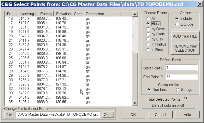
Elevation
You can specify the elevation for a given point ID using an
Elevation record.
Scale
You may specify a scale factor in a Scale record. A scale
factor is a decimal number. You may enter as many scale
factors as you wish. A scale factor will be used until another is
encountered. Scale factors should be placed before an Instrument
Point record.
Note: Multiple Traverses:
If you are combining more than one traverse in a single raw data
file, you must separate the traverses with special records. After
inserting or adding a begin traverse record, you may type in a
comment regarding the traverse in the Comment column. You may
also specify the order in which the traverses are to be processed
by using the first part of the Comment field. Please see
Traverse reduction order below for more details.
Note: If you are processing
the data with SurvNET, the Scale records are ignored. SurvNET
calculates scale factors autmatically when working on State Plane
coordinates.
Beginning and/or ending a Traverse
Note: If you are processing
the data with SurvNET, Traverse Records (LT, OT, CT, ET) are
ignored. Since SurvNET adjusts all data simultaneously, it requires
no traverse definitions.
Use Loop Traverse,
Open Traverse and
Closed Traverse records to
delineate multiple traverses within a single file.
Traverse reduction
order
The order in which the traverses appear in the raw data file is
typically not important. Traverses are processed in the order
in which they appear in the file. Traverses may be entered in a
sequential order or you may embed one traverse within
another. However, if the
coordinates computed from one traverse are needed for the reduction
of another traverse, then traverse order IS important.
If this condition is true for a raw data file and the traverses
have NOT been placed in the raw data file in the correct order,
then you need to specify a Traverse Order Number for each traverse
in the file.
Note: If you specify
Traverse Order Numbers, the traverses in the file will be reduced
in the order of their Traverse Order Numbers.
Traverse Order Numbers
Each Loop Traverse,
Open Traverse or
Closed Traverse comment
field can contain a Traverse Order Number.
Note: The Traverse
Order Number must be an integer and must appear as the first entry
in the Comment field separated from the remainder of the comment by
a space.
For example, the comment field of a Loop Traverse record having a
Traverse Order Number of 3
should look like this:
3 this is a comment
If
any one Begin Traverse
record has a Traverse
Order Number, then
all
Begin
Traverse records MUST have
a Traverse Order Number. Also, the Traverse Order Numbers in
a given file must begin with 1 and continue sequentially. You
may not duplicate a Traverse Order Number for any Begin Traverse
record in a given file.
IMPORTANT NOTE: Reducing a
raw data file having Traverse
Order Numbers that violate any of the above specifications
will have unpredictable results. Error messages during the
reduction process may not reflect the fact that improper traverse
order numbering is actually the root cause of the problem.
Loop Traverse
This record indicates the beginning of a loop traverse. A
loop traverse begins and ends at the same point. If you wish
to add a comment to identify the traverse in some way, just type it
in the Comment column.
Closed Traverse
This record indicates the beginning of a closed traverse. A
closed traverse ties into known points at both ends. If you
wish to add a comment to identify the traverse in some way, just
type it in the Comment column.
Note: If you are running a Closed
Traverse and tying into a single point, a reference azimuth must be
placed at the last instrument point if you wish to adjust the
angular error.
Open Traverse
This record indicates the beginning of an open traverse. An
open traverse is a group of side shots. If you wish to add a
comment to identify the traverse in some way, use the Comment column.
End Traverse
Signals the end of the data records for any of the traverse
types.
Comment
Inserts a comment line above the current active line. Comment lines
are ignored during processing.
Data On/Off
Data On/Off records
surround a series of records that are to be ignored during
processing by C&G or SurvNET. The first Data On/Off record encountered causes
processing to skip to the next Data On/Off record. Processing
continues beginning at the record after the second Data On/Off record. This
can be used when trying to isolate errors in a traverse.
The Add and Insert Tool bars
ADD Tool Bar: add the
various types of traverse records to the end of the current file.
 Insert
Tool Bar: insert one of the various types of traverse
records above the current record.
Insert
Tool Bar: insert one of the various types of traverse
records above the current record.
Notice that the only difference
between the appearance of the Add Toolbar and the Insert Toolbar
above is the check mark in the lower right hand corner of each icon
of the Insert Toolbar.
Toolbar Icon Explanation
IP Add/Insert an Instrument Point
record
FS Add/Insert a Foresight record
FT Add/Insert a Foresight Tie record
DR Add/Insert a Reference Bearing record
S Add/Insert a Scale record
C Add/Insert a known Coordinate
point record
E Add/Insert an Elevation
benchmark record
LT Add/Insert a Loop Traverse record
OT Add/Insert a nOpen Traverse record
CT Add/Insert a Closed Traverse record
ET Add/Insert an End Traverse record
SE Add/Insert a Standard Error record for
Network Least Squares Adjustment (SurvNET) program
Co Add/Insert a Comment record
DO Add/Insert a Data On/Off record
The Least Squares Toolbar

The "network" icon:
Selecting this icon will start the SurvNET Network Least Squares
program. If SurvNET
has already been started, clicking this icon will bring it to the
front so you can work with it. (See the Tools nenu section and the SurvNET section for additional
info.)
The “eyeball”
icon:
This icon brings up a separate window displaying a scaled map of
the current raw data file. (See Graphic View under the View
menu section)
The “C” icon:
Clicking this icon hides all Comment records. The Comment records still remain in the raw
file, they are just not shown on the screen. You will find
that there are some actions you cannot perform when Comments are
off.
The "No DO" icon:
Clicking this icon removes all the Data On/Off records from the raw data
file.
Status bar
When this menu item is checked, the status bar will display.
The status bar is along the bottom border of the CGEditor window. On the left side
of the status bar a brief help message is displayed when you hold
the cursor over such things as menu items or toolbar icons.
It also has indicators that tell you if Caps Lock or Num Lock are
turned on and displays the Row/record number that is currently
active.
Graphic View
Clicking on this menu item brings up a window containing a graphic
representation of the traverse. The traverse lines and points
are drawn to scale using the data from the current raw data
file.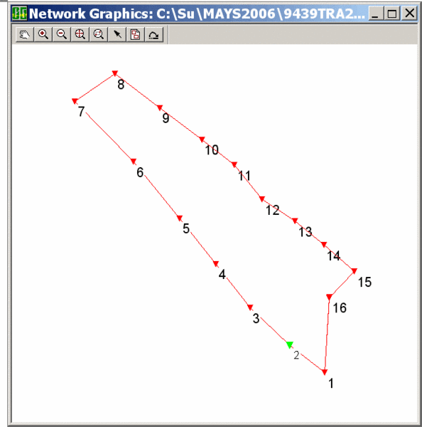 The
Graphic View Window
The
Graphic View Window
The Graphic View window shows a scaled drawing of the
current raw file traverse lines and points. The toolbar icons at
the top of the window can be used to move around in the view and
change its appearance. The icons will be discussed as they appear
from left to right:
 Pan: This works very much
like the CAD Pan command. When you click the hand icon the cursor
changes to a hand. When you click on the graphic screen the first
time you are “grabbing” the graphic. You can then move it to the
proper view and click a second time to “put it down”. You may
repeat this as many times as you wish in order to move around the
drawing. When done with the Pan command, click on the Pick Point
icon.
Pan: This works very much
like the CAD Pan command. When you click the hand icon the cursor
changes to a hand. When you click on the graphic screen the first
time you are “grabbing” the graphic. You can then move it to the
proper view and click a second time to “put it down”. You may
repeat this as many times as you wish in order to move around the
drawing. When done with the Pan command, click on the Pick Point
icon.
 Zoom In: Clicking on this
icon causes the graphic image to be enlarged a preset amount. The
zoom factor cannot be configured. If you wish to see a
certain area of the graphic image it is recommended that you click
Zoom Extents then use Zoom Window to view the desired area.
Zoom In: Clicking on this
icon causes the graphic image to be enlarged a preset amount. The
zoom factor cannot be configured. If you wish to see a
certain area of the graphic image it is recommended that you click
Zoom Extents then use Zoom Window to view the desired area.
 Zoom Out: As with Zoom
In, Zoom Out reduces the image size a pre set amount. The zoom
factor is not configurable.
Zoom Out: As with Zoom
In, Zoom Out reduces the image size a pre set amount. The zoom
factor is not configurable.
 Zoom Extents: Zooms the
image so all points and lines can be seen on the screen.
Zoom Extents: Zooms the
image so all points and lines can be seen on the screen.
 Zoom Window: Allows
you to click on two diagonal corners of the rectangular area that
you wish to see.
Zoom Window: Allows
you to click on two diagonal corners of the rectangular area that
you wish to see.
 Pick Point: Use this
icon to allow you to pick a point on the graphics screen in order
to “zoom” to the first instance of the associated point ID found in
the raw data editor window. This allows you to rapidly and
conveniently locate a given point ID in the data file. This
is especially useful in trouble shooting for errors or other
problems in the data that may be more easily detected in the
graphic image than when viewing the raw data. When you pick near a
plotted point on the graphics screen its point ID is noted.
The raw data file is then searched for that point ID. The
active field in the editor window is then set to the first instance
of that point ID. You can pick the same location several
times to move to the next instance of the point ID in the file. If
you have a large Pick Radius set (See Graphic Settings) or are
zoomed out, picking a point may result in more than one point being
found. If this occurs, a dialog box listing the nearby points
will pop up. Using the list box in the dialog choose the
desired point ID and press <Enter> or click OK to find the
point in the data file.
Pick Point: Use this
icon to allow you to pick a point on the graphics screen in order
to “zoom” to the first instance of the associated point ID found in
the raw data editor window. This allows you to rapidly and
conveniently locate a given point ID in the data file. This
is especially useful in trouble shooting for errors or other
problems in the data that may be more easily detected in the
graphic image than when viewing the raw data. When you pick near a
plotted point on the graphics screen its point ID is noted.
The raw data file is then searched for that point ID. The
active field in the editor window is then set to the first instance
of that point ID. You can pick the same location several
times to move to the next instance of the point ID in the file. If
you have a large Pick Radius set (See Graphic Settings) or are
zoomed out, picking a point may result in more than one point being
found. If this occurs, a dialog box listing the nearby points
will pop up. Using the list box in the dialog choose the
desired point ID and press <Enter> or click OK to find the
point in the data file.
Clicking this icon also allows you to turn off the Pan feature when
you are done panning.  Brings up the
Graphic Settings
dialog:
Brings up the
Graphic Settings
dialog: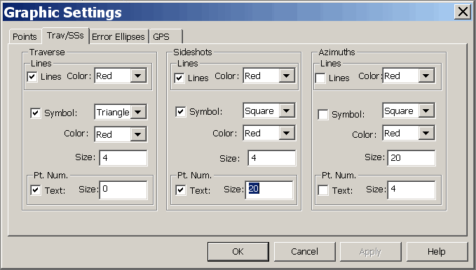 The graphic settings dialog
allows you to configure the appearance of the various items that
may be seen on the graphics screen.
The graphic settings dialog
allows you to configure the appearance of the various items that
may be seen on the graphics screen.
Note: The Graphic Settings dialog is also used
for the SurvNET program and
thus the items on the Error
Ellipses and GPS
tabs have no effect on the CGEditor Graphic View.
Points and Trav/SSs tabs
Control Points, Fixed Control
Points and Floating Points and Traverse, Sideshots and
Azimuths:
Specify whether the symbols, labels
or lines for any of these should be shown. Also, if they are
to be shown, specify symbol and/or line color, symbol type and
point ID label size.
Symbol:
Choose to represent the various
types of points as a Square, Triangle or Circle using the drop down
list.
Color:
For symbol or line color you can
choose Red, Green, Blue, Cyan, Magenta or Yellow from the drop down
list.
Size:
Specify the point symbol
size.
Pt. Num.
Text: Check the check box if you want
the points labeled.
Size: If the points are to
be labeled, specify the label height.
Pick Radius
When you pick near a point plotted
on the graphics screen, the current field in the editor window
moves to the first instance of that point in the current raw data
file. Setting the pick radius allows you to specify how large
an area around the pick point is to be searched for raw data points
drawn in the Graphics View window.
Error Ellipses tab (Has
no effect in CGEditor)
GPS tab (Has no effect
in CGEditor)
 Refresh Graphics: Allows
you to refresh the graphics to view recent changes in the raw data
due to editing.
Refresh Graphics: Allows
you to refresh the graphics to view recent changes in the raw data
due to editing.
Important Note: For the Refresh Graphics to reflect recent
changes in the raw data file, you must save the file itself prior
to refreshing the graphics.
Settings Menu
The items in the settings menu can be used to configure how the
data in the raw data file will be interpreted and the appearance of
that data as seen in the CGEditor.
Raw Data File Settings dialog
When you click on the Raw Data
File menu item you will see a dialog box that allows you to
specify many of the more important settings related to the
currently open raw data files. You can also set up the
defaults that will be used for newly created raw data files.
Note: See the More on
Default Settings subsection at the end of the Settings Menu section. 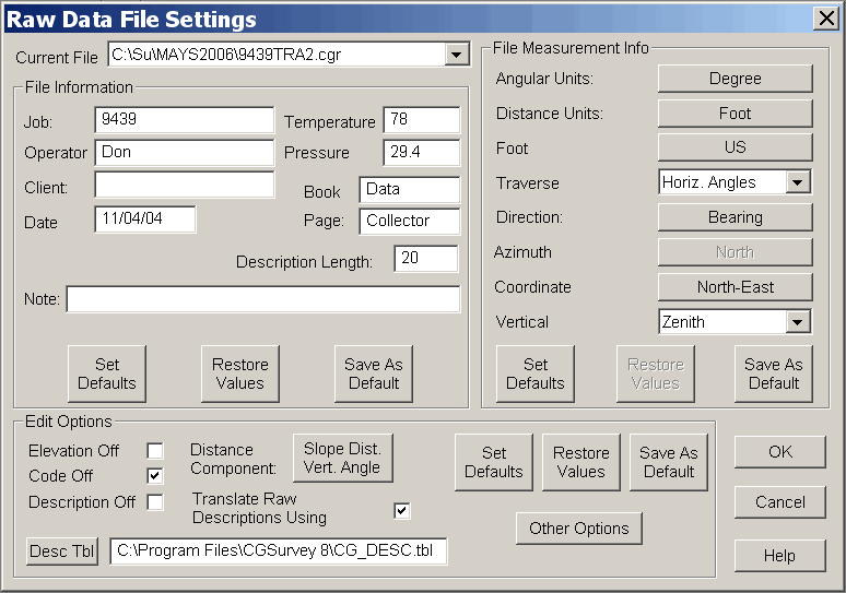
The Raw Data File Settings dialog
Current File
To view and/or edit the settings for a given file, pick the file
using the Current File list
box. You can also view and/or edit the DEFAULT settings for newly created
files.
File Information
This portion of the dialog allows the user to specify job or
project specific information. Except for description length, these
items are for your own information and do not affect processing of
the raw data.
Job: Enter any name you
wish to identify the job or project.
Operator: Enter the name of
the person who led the field work.
Client: The name of the
person or company for whom this work was done.
Date: Date in any format
you wish to use.
Temperature: Temperature at
the time the field work was done. For your reference
only. May be Celsius or Fahrenheit.
Pressure: Atmospheric
pressure at the time the field work was done. For your
reference only. May be in any units.
Book: Field book number for
the field work.
Page: Page number in the
field book.
Description Length: Specify
the length of the description field used in this file.
Set Defaults:
This button sets the items in the
File Information portion of
the dialog as the current default values. When a new raw data
file is created, these default settings will be used. See the
More on Default Settings
heading at the end of the Settings section.
Restore Values:
This button allows you to set the
values in the File Information portion of the dialog back to what
they were when you opened the Raw
Data File Settings dialog.
Save As Default:
Sets the default values for the
File Information portion of
the dialog. These values are used as the default settings
when a new file is created. See the More on Default Settings heading at the
end of the Settings
section.
File Measurement Info
Angular Units: Clicking the
button to the right changes the angular units from Degrees to Grads or vice versa.
Distance Units: Clicking
the button to the right changes the distance units from
Foot to Meter or vice versa.
Foot Definition: Clicking
the button to the right changes the foot definition from
US feet to International feet or vice versa.
This button is only active when Distance Units are set to Foot.
Traverse Angles: Choose one
of the items in the list to specify how the traverse angles were
measured:
1. Horiz. Angles
2. Azimuths
3. Deflection Angles
Direction:
Specify what type of angle is used
to define the direction of a line. Clicking the button to the
right changes the direction from Bearing to Azimuth or vice versa.
Azimuth Direction:
Specify the reference direction for
azimuths. Clicking the button to the right changes the
azimuth direction from North to South or vice versa. This button
is only active when Direction is set to Azimuth.
Coordinate Order: Clicking
the button to the right changes the Coordinate Order from
North-East to East-North or vice versa.
Vertical Reference: Pick
one of the items from the list to the right to specify the
reference orientation for measuring vertical angles:
1. Zenith
2. Nadir
3. Horizontal
Set Defaults:
This button sets the items in the
File Measurement Info
portion of the dialog to the current default values. See the
More on Default Settings
heading at the end of the Settings section.
Restore Values:
This button allows you to set the
values in the File Measurement
Info portion of the dialog back to what they were when you
opened the Raw Data File
Settings dialog.
Save As Default:
Sets the default values for the
File Measurement Info
portion of the dialog. These values are used as the default
settings when a new file is created. See the More on Default Settings heading at the
end of the Settings section.
Edit Options
Elevation Off:
Check this check box to turn off
the Elevation data entry column for this file. This makes
data input more convenient since you do not have to enter any data
in the Elevation column, nor do you have to tab through it.
Turning off elevations does not cause any data to be deleted from
the current file.
Code Off:
Check this check box to turn off
the Code data entry column for this file. This makes data
input more convenient since you will not have to enter any data in
the Code column. Turning off codes does not cause any data to
be deleted from the current file.
Description Off:
Check this check box to turn off
the Description data entry column for this file. This makes
data input more convenient since you will not have to enter any
data in the Description column. Turning off descriptions does
not cause any data to be deleted from the current file.
Note: You can turn the Elevation, Code and Description data
entry columns on or off while editing a file by clicking on the
column heading.
Distance Component:
Specify how distances are to be
entered. Clicking the button to the right changes the
Distance Component from Slope Dist-Vert Angle to Horiz. Dist-Vert.
Dist. or vice versa.
Translate Raw Descriptions Using
Description Table:
This check box is only active if
descriptions are on. If you check this check box, integer
codes entered in the Description field will be looked up in the
specified description table (See the following item.). If a
matching description number is found in the description table, the
code will be moved to the Code field and the description found in
the description table will be placed in the Description
field. If no matching description number is found, the
Description field remains as entered.
Desc Tbl:
Click on the Desc Tbl button use a
file dialog to set or change the description table. The
description table is used to set the Description field when an
integer number is entered in the Description field. (See the
previous item.) If you prefer, instead of clicking on the Desc Tbl
button you can also type in the full file path in the edit box.
Set Defaults:
This button sets the items in the
Edit Options portion of the dialog to the current default
values. See the More on Default Settings heading at the end
of the Settings section.
Restore Values:
This button allows you to set the
values in the Edit Options portion of the dialog back to what they
were when you opened the Raw Data File Settings dialog.
Save As Default:
Sets the default values for the
Edit Options portion of the dialog. These values are used as
the default settings when a new file is created. See the More
on Default Settings heading at the end of the Settings section.
Other Edit Options dialog
Click the Other
Options button to bring up the Other Edit Options Dialog
box.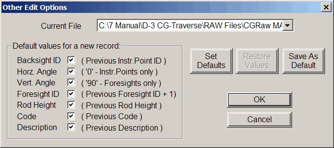 Current
File:
Current
File:
Click on the name of the file in
the file list for which you wish to review and/or specify the
settings. You can also choose to view or edit the DEFAULT
settings.
Default values for new
record:
Checking the check box for the following items causes CGEditor to
“remember” the most recently entered value in the respective
field. Thus when you insert or add a record containing one of
the checked items, it will be filled in with a “default” value.
Backsight ID
Horz. Angle
Vert. Angle
Foresight ID
Rod Height
Code
Description
Note: The previously used field values
are not “remembered” and thus will not be used to fill in new
records the next time you open the CGEditor.
Set Defaults:
This button sets the items in the
Other Edit Options dialog to the current default values. See
More on Default Settings at the end of the Settings section.
Restore Values:
This button allows you to set the
values in the Other Edit Options dialog back to what they were when
you opened the Raw Data File Settings dialog.
Save As Default:
Sets the default values for the
items found in the Other Edit Options dialog. These values
are used as the default settings when a new file is created.
See More on Default Settings at the end of the Settings
section.
Click OK to close the
Other Edit Options
dialog.
Click OK to close the
Raw Data File Settings
dialog.
More on Default Settings:
When the CGEditor is started from CGSurvey, many of the initial
default settings may not be those you had specified in a previous
session. This is because many of the default settings you
previously specified where overridden by the current CG Settings
specified in CGSurvey. However, you may yourself
override the default settings for the current session only by
changing any of the settings and clicking the Save As Default
button. If you wish to change the “default” settings for
future editing sessions, you must change the CG Settings in
CGSurvey.
Settings overridden by the settings on the various tabs in the
CAD C&G Options dialog:
File Information: only
Description Length is
overridden by the settings in the CAD C&G Options dialog.
File Measurement Info: ALL
items are overridden by the settings in the CAD C&G Options dialog.
Edit Options: ALL items are
overridden by the settings in the CAD C&G Options dialog.
Other Edit Options: NONE
are overridden by the settings in the CAD C&G Options dialog.
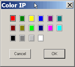
Record Color
To set the color for a given record type click the Record Color menu item. Then, in
the Record Color dialog,
click on the record type and a color selection dialog will appear.
Click on the color you want the that record type to have. If
you click the Set Defaults
button, the original program default colors are set. Click
the OK button to save the
color settings and close the dialog. Click the Cancel button to close the dialog
without saving the changes.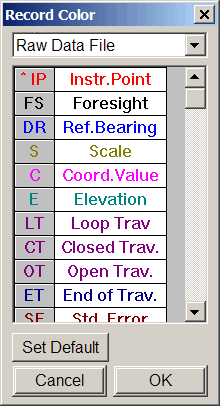
Validate Records
If this menu item is checked , all the records in the file will be
validated prior to saving the file. To change the Validate
Record setting, just click the menu item. If an invalid
record is encountered when saving a file with the Validate Records
menu item checked, you are asked if you want to edit the invalid
field, ignore the error or ignore all errors. If you decide
to edit the offending field, the field will be highlighted and you
can edit it and attempt to save again.
Tools Menu
The Tools menu has several items that can be used to find and
replace specific text in specific types of fields. It even
allows you to apply simple mathematical functions to allow you to
edit the data in a group of fields in a single step.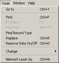
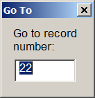
Goto (Ctrl + T):
Select this item to go to a certain row (or record) number.
In the dialog box that comes up, type in the desired row number and
click OK. The editor window will zoom to that record and set
the current field to the first editable field in the record.
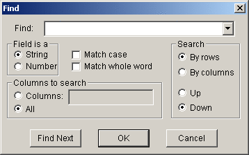
Find (Ctrl + f) menu item:
The Find dialog allows you
to enter a value to find and set the detailed search criteria.
Find: Type in the string or
number you are searching for in the edit box or pick a previous
search string from the list.
Field is a: Choose what
type of data is in the field you are looking for. Check
appropriate checkbox for matching case and/or whole word.
Columns to search:
The default is to search
All columns, but if you
choose the Columns radio
button, you can enter a comma separated list of column
numbers. The column to the right of the TYPE column is
column 1 and it is the first column in which you can
search.
Search:
You can search By Rows or By Columns and you can choose to search
Up or Down from the current field.
Once you have specified the parameters for the search, click the
Find Next button to find
the first instance of the search string. Continue to click
the Find Next button to
find the next instance of the string. To just find the next
instance of a string and close the dialog box, you can click
OK.
Find Next (F3) menu item:
Finds to the next occurrence of the string previously specified in
the Find dialog.
Find Prev (<Shift> +
<F3>) menu item: Moves you to the previous occurrence
of the string previously specified in the Find dialog.
Find Record Type menu item:
Allows you to find the next record type of the type
specified. The search starts at the current record.
When you click this menu item, the Find Record Type dialog box is
displayed. Choose the record type you wish to look for by
picking from the list then specify the direction of search and
click the Find Next button
to find the record. Click Cancel when done.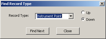 Replace
(<Ctrl> + r) menu item: When you click on this menu
item, the Replace dialog
appears.
Replace
(<Ctrl> + r) menu item: When you click on this menu
item, the Replace dialog
appears.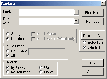 The Replace dialog allows you to specify a
Find: value and a
Replace with: value.
The other fields in the Replace dialog are the same as the
Find dialog. You can
view the Find: value one
instance at a time by clicking the Find Next button, if you decide to
replace a given value found just click the Replace button.
Alternatively, you can allow the software to automatically replace
all the instances of the Find: value encountered in the
specified columns in the raw data file by clicking the Replace All button.
The Replace dialog allows you to specify a
Find: value and a
Replace with: value.
The other fields in the Replace dialog are the same as the
Find dialog. You can
view the Find: value one
instance at a time by clicking the Find Next button, if you decide to
replace a given value found just click the Replace button.
Alternatively, you can allow the software to automatically replace
all the instances of the Find: value encountered in the
specified columns in the raw data file by clicking the Replace All button.
Note: Before clicking the
Replace All button, be sure
to specify whether you wish to replace matching fields in the
highlighted Selection of
fields/records or in all the fields in the Whole File.
Data On/Off (<Ctrl> + d) menu item:
Selecting this menu item inserts a Data On/Off record above the
current record. Records between pairs of Data On/Off records
are ignored when the traverse is reduced. This can be useful when
trying to find problems in a traverse.
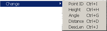
Change
The items in this submenu allow you to change specific types of
fields in the raw data file.
Point ID (<Ctrl> + I) menu
item: This menu item allows you to change point IDs for
instrument points, back sight points, or foresight points. You can
change individual points one at a time or you can make a global
change. You can specify a value to find and a value to
replace it with. The Change Point
ID dialog has several sections that are similar to the
Replace dialog 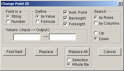 Field is
a: You must specify how you want to treat the point ID
field. You can do this by clicking on the String or Number radio buttons.
Field is
a: You must specify how you want to treat the point ID
field. You can do this by clicking on the String or Number radio buttons.
Define: You must specify
whether you wish to specify the replacement value by Value or Formula.
Note: The Values: (Input --> Output) section
of the dialog changes its title to Formula: when you elect to Define by Formula. Also, the content of this
portion of the dialog changes according to the field type (see
Values: or Formula: section
below).
Instr. Point, Backsight, and
Foresight check boxes: Check the check boxes of the
types of point IDs you wish to change.
Values: or Formula:
section
When Define is set to by Value and Field is a is specified as either a
String or a Number then the title of this section
of the dialog becomes
Values: (Input —>
Output) (as shown in the dialog above). In this
configuration the Change Point
ID dialog functions like the Replace dialog except that it only
searches the point ID fields specified.
Specify the value to search for in the edit box to the left of the
"-->" and the value to replace it with in the edit box to the
right of the "-->".
The Find Next, Replace and Replace All buttons act exactly the
same as the Find Next,
Replace and Replace All buttons in the Replace dialog.
When Define is set to Formula the title of this section of
the dialog becomes Formula:
If Field is a is specified as a
String, the dialog is as
shown below:
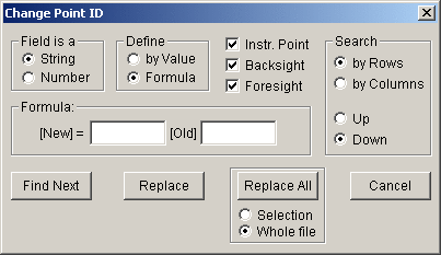
In this configuration the formula
acts to add a prefix and/or a suffix to the existing point ID
(represented by [Old]). Enter the prefix in the
edit box to the left of [Old] and the suffix in the edit box to
the right of [Old].
If you do not wish to add a prefix or you do not wish to add a
suffix, you may leave either the left or right hand edit boxes
empty.
If Field is a is specified as a
Number, the dialog is as
shown below:
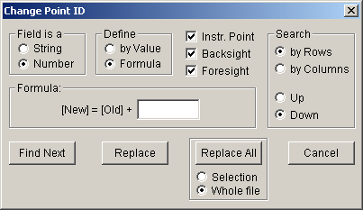
In this configuration the formula
adds a specified number to a given point ID. Enter the
positive or negative number in the edit box to the right of
"[Old] +".
NOTE: When the Field is a is specified as a
Number and a point ID
containing non-numeric characters is encountered, it will be
skipped and no change will be made to it.
Change Height (<Ctrl> + h)
Use this menu item to change the instrument height and/or rod
height. Clicking this menu item brings up the Change Height dialog.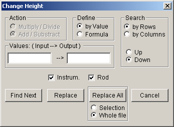 Action section of dialog
Use this
section to determine how the height is to be changed when
Define is set to
Formula.
Multiply/Divide: Choose
this if you wish to multiply or divide the height by a given
number.
Add/Subtract: Choose this
if you wish to add a specified number to the height or subtract a
specified number from the height.
Define section of
dialog by Value:
If you choose
by Value, this command becomes
like the Replace command, except that it acts only on instrument
heights and/or rod heights.
Formula: This allows you to
specify a number to apply to the height by addition, subtraction,
multiplication, or division. (See the Action and Values:/Formula: sections.)
Values:/Formula: section of
dialog
Depending on what you choose in the Action and Define sections
there are several possibilities for this section of the dialog:
When
Define is set to
by Value the
Action section of dialog is disabled
and the title of this section becomes
Values: (Input—>Output)
In this configuration the feature functions like the
Replace command, except that it acts
only on instrument heights and/or rod heights.
When
Define is set to
Formula, the
Action section of dialog is enabled and
the title of this section becomes
Formula:
When the Action is set to Multiply/Divide, the Formula: section changes as seen
below:
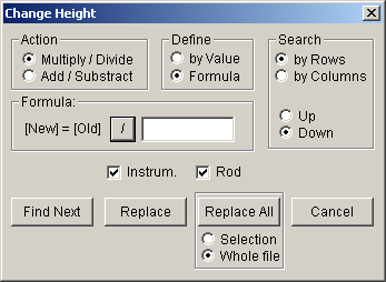
In this configuration you can
multiply or divide the instrument height or rod height by the
number specified in the edit box. To switch between multiply
and divide, just click on the button with the multiply ("*") or
divide ("/") symbol on it.
When
Action is set to
Add/Subtract, the
Formula: section changes as seen
below:
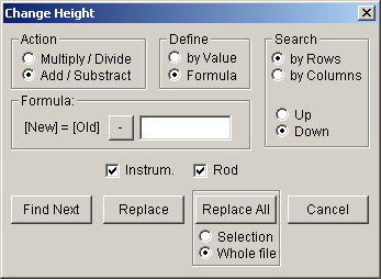
In this configuration you can add
or subtract the number specified in the edit box to or from the
instrument height or rod height. To switch between add and
subtract, just click on the button with the add ("+") or subtract
("-") symbol on it.
Search section of the
dialog
Use this section of the dialog to
specify how the records will be searched. The search begins
at the currently active field.
Instrum. and Rod checkboxes: Check one or both of
these check boxes to specify which types of heights are to be
searched/changed.
Find Next
button: Use this button to
move to the next field that matches the specifications you
entered.
Replace button: Use this
button to replace the highlighted text that was found.
Change All button: Use this
button to make the changes specified to all matching fields in the
file. Be sure to specify whether to apply the changes to the
highlighted Selection
(records or fields) or to the Whole file.
Cancel button: Click the
Cancel button to close the dialog.
Change Angle (<Ctrl> + g)
Choose this menu item to change vertical and/or horizontal angle
fields. Clicking the Change
Angle menu item brings up the Change Angle dialog: This dialog is
almost identical to the Change
Height dialog and will not be described in detail. The
differences are: the Multiply/Divide action seen in the
Change Height dialog is
replaced by the Make
Opposite action; you can check either the Vertical or
Horizontal check boxes to specify the angles you wish to change;
choosing Formula and
Make Opposite disables the
Formula: section of the
dialog due to the fact that the action to be taken is merely to
reverse the sign of the angle.
Change Distance (<Ctrl> + D)
The Change Distance dialog
is almost identical to the Change
Height dialog. The only difference is that you can
choose to change the Slope
distance and/or the Horizontal distance by checking the
checkboxes.
Change DescLen (<Ctrl> + j)
This command allows you to set the description length for the
current raw data file. It displays the Longest description length: that is
found in the current records in the file. It allows you to
specify a new Description
length:.
Warning: If you specify a
length less than the longest description found in the file, the
descriptions that exceed that length will be truncated.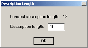 Network
Least Sq. menu item
Network
Least Sq. menu item
This menu item runs the SurvNET Network Least Squares
Adjustment program. Please refer to the section on
SurvNET for a detailed description of this very powerful traverse
and level loop adjustment program.
Window menu
This menu contains many of the standard Window menu items found in
other programs. It allows you to arrange the currently open
windows in several configurations. It has the added
functionality of the New Window command which allows you to have
two or more views of a single file
Help
For information regarding the CGEditor program version click the
About CGEditor... menu item.
Editing C&G Mapcheck Files
Mapcheck files are typically used to check the closure of a
given parcel of land given the deed description of that
parcel. A mapcheck file may contain straight line boundaries
as well as boundaries described by both tangent and non-tangent
curves.
Creating or Opening a Mapcheck
File
To create a new file or open an existing file choose
File on the main menu then
either click New or
Open.
If you choose New a submenu
will appear, click the C&G
Mapcheck File menu item.
In either case you will then see a file dialog. Browse to the
directory where you wish to work and, if creating a new file, type
in a file name, or, if opening an existing file, click on a
mapcheck file (*.cgm). Next, click the Save button for a new file or the
Open button for an existing
file.
If you are creating a new file, an empty file will be shown in its
own document window within the editor. If you are editing an
existing file, the data from the file will appear in a similar
document window. It is possible to have multiple documents
open at the same time. So you could create a new file and
open an existing file in the same editing session and each would
appear in its own window in the editor. You can have as many
new and/or existing files open as your project demands. You
may also cut, copy and/or paste between files.
Settings: Before entering
any data you should check the current settings. Click the
Settings menu item then
click Map Check File to
review and/or change the current settings. (For more details,
see the Settings Menu
section of Editing C&G
Mapcheck Files.)
Mapcheck Data Entry
Opening an existing template file or creating a new one is very
similar to opening or creating a raw traverse data file.
There are three types of records that you may use in a mapcheck
file:
Straight line (identified as
Line in the Type column)
Tangent Curve (identified
as TC in the Type column)
Non-tangent Curve
(identified as NTC-C or
NTC-R in the Type column for Chord or Radius
definition NTC records)
Adding and Inserting new
records
To create a new record in the
current file you must either use the Add or Insert menu item or the Add or Insert toolbar.
Note: If the Add and/or Insert toolbars are not showing, click
the View menu then choose
the menu item for the toolbar you want to turn show.
When you click on one of the Add menu items or toolbar icons, an
empty record is added to the end of the file. If you click on
one of the Insert menu
items or toolbar icons, an empty record is inserted above the
currently active record or field. To make a record the
currently active record, just click on one of its fields.
Moving from field to field:
While entering data, to move to the next field, press the Enter or
Tab key. To move to the preceding field press the Esc key or
the Shift and Tab keys at the same time.
Straight Lines
There are two fields to be filled out in a Straight Line (or Line) record:
Bearing or Azimuth: For a
bearing, use the standard C&G bearing notation:
For Bearing: Qdd.mmsss
Where
q = quadrant (1 = NE, 2 = SE, 3 =
SW, 4 = NW)
d = 2 digit bearing
m = minutes
s = seconds and tenths of seconds
For example: enter S 35° 22’ 34.2”
E as 235.22342
For Azimuth, use the notation:
ddd.mmsss
Distance: Enter the length
of the boundary in whatever units you have specified in the
Map Check File
Settings.
Code: Enter a code
(optional).
Note: If Code Off is checked in the Map Check File Settings dialog, this
field will not be active. However, clicking on the
Code column title will turn
it on.
Description: Enter a
description (optional).
Note: If Description Off is checked in the
Map Check File Settings
dialog, this field will not be active. However, clicking on
the Description column
title will turn it on.
If Translate Mapcheck Descriptions Using a
Description Table is checked in the Map Check File Settings dialog and you
have entered an integer number description, then when you move to
the next field, the description table will be searched for a
description number matching the integer entered. If a
matching description number is found, the description from the
table will be placed in the Description field and the integer
originally entered in the Description field will be placed in the
Code field.
Tangent Curves
For a Tangent Curve record there are six possible fields to
enter. Of the following six fields you must enter data for
two of the first four:
Radius - decimal distance
Arc Length - decimal
distance
Chord - decimal
distance
Central Angle - angle
specified as ddd.mmsss (degrees.minutes and seconds to nearest .1
sec.)
Code (optional - see
Straight Lines above)
Description (optional - see
Straight Lines above)
Non-Tangent Curves
The fields in a Non-Tangent
Curve record vary according to whether it is defined using
the chord bearing/azimuth or radius bearing/azimuth.
When using Non-Tangent
Curve record it is necessary to specify whether the chord or
radius definition will be used when specifying the curve .
There are four ways to accomplish this:
- Prior to Inserting or Adding the record, use the Settings menu then choose Map Check File. In the
Map Check File Settings
dialog set the Curve
Definition in the File
Measurement Info section of the dialog.
- Prior to Inserting or Adding the record, use the Settings menu to check or uncheck the
Non-Tan Curves Use Chord
menu item. When the Non-Tan
Curves Use Chord menu item is checked, newly created
Non-Tangent Curve records
will added or inserted that use the chord definition, otherwise
they will use the radius definition.
- Prior to Inserting or Adding the record, click the C-R toolbar icon. When the icon appears depressed,
newly created Non-Tangent
Curve records will use the chord definition, otherwise they
will use the radius definition.
- To change the type of curve definition for an existing
Non-Tangent Curve record,
use the Edit main menu and choose the Change Curve Def'n menu
item. This changes the current record from what it is now to
the opposite type of curve definition.
For both the Chord and
Radius definitions the
following fields are present in the record:
Chord or Radius Brg/Azimuth
used to orient the curve properly
as it leaves the PC. As noted in the Tangent Curves section, bearings must
be entered in the qdd.mmsss format and azimuths entered in the
ddd.mmsss format.
Radius
Arc Length
Chord
Central Ang
Code
Description
All but the first field has been discussed earlier in the
Tangent Curves section and
will not be described here.
Editing a Mapcheck File
Most of the menu items found in the mapcheck menus have been
discussed in the Editing Traverse
Raw Data Files section. Only the differences will be
discussed here.
File Menu: The File menu when editing a mapcheck file
is identical to the File
menu discussed in the Editing
Traverse Raw Data Files section.
Edit Menu: With the
exception of the Change Curve
Def’n menu item, the Edit menu is identical to the
Edit menu discussed in the
Editing Traverse Raw Data
Files section. Change
Curve Def’n was discussed above in the Non-Tangent Curves section
Add Menu: The Add menu
allows you to add Straight
line, Tangent Curve
and Non-Tangent Curve
records to the end of the file.
Insert Menu: The Insert
menu allows you to insert Straight
line, Tangent Curve
and Non-Tangent Curve
records above the current record.
View Menu: Allows you to
turn the toolbars on and off.
Settings Menu
The Settings menu contains
items that allow you to specify the format of the data in a
mapcheck file and how this data will appear in the CGEditor.
Map Check File settings menu
item
The Map Check
File menu item brings up the Map Check File Settings dialog (see
below). This dialog allows you to specify settings for each
of the mapcheck files currently open in the editor. It also
allows you to specify the default settings for creating new map
check files.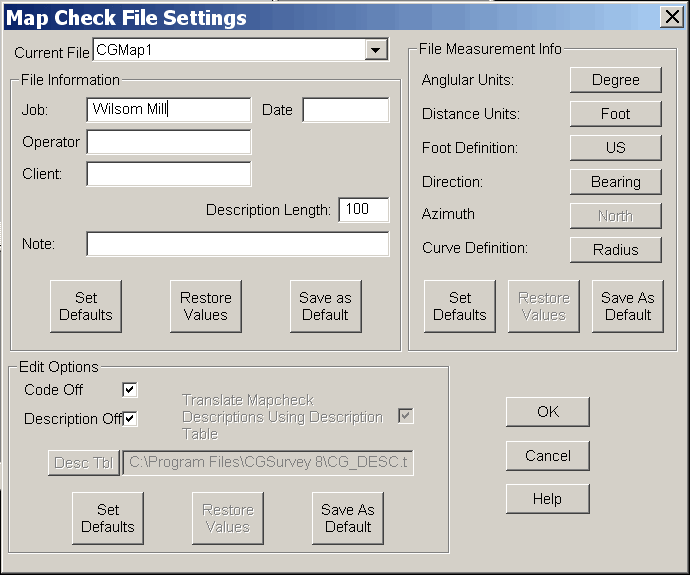 Current File: Use this list to choose a
file you wish to set or view the settings for. You may also
set or view the DEFAULT
settings that are used for newly created files.
Current File: Use this list to choose a
file you wish to set or view the settings for. You may also
set or view the DEFAULT
settings that are used for newly created files.
File Information and Edit
Options:
The settings in the File
Information and Edit Options sections have been discussed under the
Settings Menu section of Editing a Raw Data File.
File Measurement Info:
Most of the settings in the File
Measurement Info section have been discussed under the Settings
Menu section of Editing a Raw Data File. However, a
Curve Definition: item has
been added to this section for mapcheck files:
Curve Definition: click the
Curve Definition button to
change from Chord to Radius definitions and vice versa.
Curve Definition only
applies to the insertion or addition of Non-Tangent Curve records.
Record Color menu item
The Record Color menu item
has been discussed under the Settings Menu section of Editing Traverse Raw Data Files.
The only difference is that here you are setting the colors for the
various types of mapcheck records instead of raw data records.
Validate Records
This menu item allows you to set whether records are
validated prior to being saved. (See also, Validate Records in the Settings Menu section of Editing Traverse Raw Data Files.)
Non-Tan Curves Use Chord:
Use this to switch which types of Non-Tangent Curve records are added or
inserted.
Tools, Window and Help Menus the items in these menus
have been discussed in the Editing
Traverse Raw Data Files section
C&G Cross Section Files
Cross section files contain data which defines one or more
topographic or design cross sections along an alignment. Any
features using a cross section file assume that it is at right
angles to the alignment. Each cross section is identified by
its station along the alignment. Each cross section is
defined by a Station record
specifying a station on the alignment followed by a series of
Point records specifying
the offset and elevation of points on the cross section at that
station. Cross sections can be used to visualize a site,
specify design elevations and calculate volumes. Opening an
existing cross section file or creating a new one is very similar
to opening or creating a map check file.
Cross Section File Data Entry
Station Records: There are
three fields to be filled out in a Station record:
Station: Specifies the station of this
cross section along the alignment. For example: station 6+45.37 is
indicated as 645.37.
Left Slope:
This field defines the slope at the
left side of the cross section in feet per foot (or meters per
meter if units are set to meters). This slope will be used to
extend this cross section to meet any cross section it
overlays.
Right Slope:
This field defines the slope at the
right side of the cross section in feet/foot (meters/meter).
This slope will be used to extend this cross section to meet any
cross section it overlays.
Point Records
There are two fields in a Point record:
Offset: The Offset defines the perpendicular
distance from the alignment to this point on the cross section.
Elevation: The Elevation
specifies the elevation of this point on the cross
section.
Cross Section File Data Editing
Adding and Inserting new records: To create a new record in the
current file you must either use the Add or Insert menu or toolbars.
Note: If the toolbars are
not showing, click on the View menu then click the item for the
toolbar you want to turn on.
Settings Menu item
Record Color:
The Record Color menu item has been
discussed under the Settings
Menu section of Editing
Traverse Raw Data Files. The only difference is that
here you are setting the colors for the various types of cross
section records instead of raw data records.
Validate Records: This menu
item has been described in the Settings Menu section of Editing Traverse Raw Data Files
US Foot: If this
menu item is checked units are US feet. If the Meters menu item is checked, this menu
item is disabled.
International foot: If this
menu item is checked units are International feet. If
the Meters menu item is
checked, this menu item is disabled.
Feet: If this menu item is
checked units are Feet.
Meters: If this menu item
is checked units are meters.
Note: The settings for US Foot and
International foot will be ignored if Meters is checked.
C&G Template Files
Template files contain data defining standard cross section
templates that can be used to create a cross section file that
represents the design cross sections for a proposed
alignment. Cross section files created using templates can be
overlaid on existing cross sections to allow the computation of cut
and fill volumes and to visualize the design alignment. Opening an
existing template file or creating a new one is very similar to
opening or creating a map check file.
Entering and Editing Template Data
Entering and editing template data is analogous to that described
in Entering and Editing Cross
Section Data except that, instead of being identified by
their station along the alignment, templates are identified by an
integer template identifier. This identifier is used when
building a cross section from templates in order to specify a
template among the many that a template file may
contain. Templates are placed along a proposed
alignment at various stations and thus create a series of cross
sections using the alignment elevation to set the elevation of the
template points. When building cross sections along an
alignment using templates, cross sections at stations between two
template stations result in a series of cross sections being
created to transition between the templates.
Template File Data Entry
Template Records: There are
five fields to be filled out in a Template record:
Template: Template number for
identifying the template
Left Slope:
Specifies the slope at the left
side of the template in feet/foot (meters/meter).
This slope will be used to extend this template generated cross
section to meet any cross section it overlays.
Right Slope:
Enter the slope at the right side
of the template in feet per foot (or meters per meter units are set
to meters). This slope will be used to extend this template
generated cross section to meet any cross section it
overlays.
Offset:
The Offset defines the distance
from the centerline of the template to this point on the cross
section. The template centerline should be assigned a 0.0
offset. The 0.0 offset is placed on the alignment when cross
sections are generated from templates.
Elevation:
The Elevation specifies the
elevation of this point on the template. If the elevation of
the centerline point is set to 0.0, then this elevation can be used
to directly compute the elevation of the point based on the
elevation of the alignment where the template is placed.
Editing a Template File:
All template menu items and editing procedures are identical to
those described for cross sections.
Editing Coordinate Files
Coordinate files contain data on the Point IDs, Northings,
Eastings, Elevations, Descriptions and, for C&G files, Codes
for various points located in the field and points created by
calculations and/or by hand data entry. The coordinate file
may have points from a single job, portions of a single job or many
jobs. The Point ID must be a unique identifier for a given
point. Typically Point IDs are integer numbers but may also
be any combination of letters and numbers depending on the format
of the file.
The CGEditor can be used to edit six different types of coordinate
files. All the supported coordinate file types have
Point ID, Northing, Easting, Elevation, and Description fields. In all
formats, any given point may have a blank Description field. The types of
files supported and a brief description of their differences
follows:
C&G Numeric (*.crd)
Point ID: any integer number between 1
and 65,536.
Description: The maximum
description length for a given file can vary between 1 and 100
characters and is set when the file is created. A given point
description entry may be blank.
Code: up to 4 characters
long. Used to filter and sort points. The Code field may be blank.
C&G Alpha-numeric
(*.cgc)
Point ID: up to 10 characters long and
can contain any combination of alphabetic and numeric
characters.
Description: The maximum
description length for a given file can vary between 1 and 100
characters and is set when the file is created. A given point
description entry may be blank.
Code: up to 4 characters
long. Used to filter and sort points. The Code field may be blank.
Carlson Numeric (*.crd)
Point ID: any positive integer number
containing 1 to 9 digits.
Description: entries can be
from 0 to 31 characters long.
(the Code field is not
supported.)
Carlson Alpha-numeric
(*.crd)
Point ID: any a series of from 1 to 9
alphabetic or numeric characters.
Description: entries can be
from 0 to 31 characters long.
(the Code field is not
supported.)
Simplicity (*.zak)
Point ID: can be any positive integer
number containing 1 to 8 digits.
Description: entries can be
from 0 to 28 characters long.
(the Code field is not
supported.)
Land Desktop (*.mdb)
Point ID: can be a series of from 1 to
255 alphabetic or numeric characters.
Description: entries can be
from 0 to 255 characters long.
(the Code field is not
supported.)
Creating or Opening a Coordinate
File
To create a new file or open an existing file choose
File on the main menu then
either click New or
Open.
If you choose New a submenu
will appear, click the Coordinate
File menu item or click on the "C" icon in the Standard toolbar. Next pick the
type of coordinate file you wish to create using the Coordinate File Type dialog: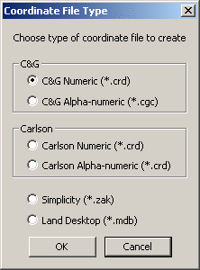 A
new coordinate file with a temporary name will appear in its own
document window in the CGEditor and will contain only a single
blank coordinate Point
record.
A
new coordinate file with a temporary name will appear in its own
document window in the CGEditor and will contain only a single
blank coordinate Point
record.
If you are opening an existing file using the Open menu item, you will be asked to
choose the file using file dialog. Browse to the directory
where you wish to work click on a coordinate file and click the
Open button The
coordinate records from the file will appear in a separate document
window in the CGEditor.
It is possible to have multiple documents open at the same
time. So you could create a new file and open an existing
file in the same editing session and each would appear in its own
window in the editor. You can have as many new and/or
existing files open as your project demands. You may also
cut, copy and/or paste between files.
Settings: Before entering
any data you should check the current settings. Click the
Settings menu item then
click Coordinate File to
review and/or change the current settings. (For more details,
see the Settings Menu
section of Editing Coordinate
Files.)
Entering and Editing Coordinate File Data
Once a coordinate file has been opened or created, you can edit any
of the fields in any of the records. To create a new
coordinate point you must use the Add/Insert main menu or
toolbar. Both the Add/Insert menu and toolbar allow you to
add or insert individual blank records or one or more records from
an existing coordinate file. When you add a record or
records, they are appended to the end of the file. When you
Insert one or more records they are inserted just above the current
record.
Insert and Adding Coordinate
Records from an Existing Coordinate File
If you choose to either the Add or Insert Pts from File or the
corresponding toolbar item, you will see the C&G Select Points from: dialog.
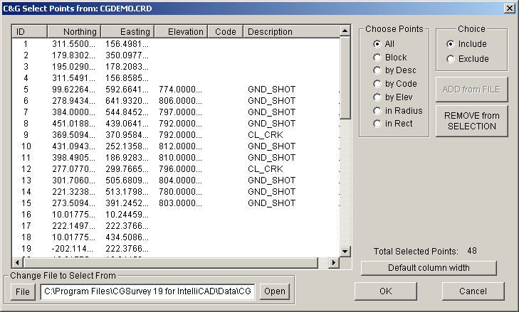 This dialog consists of a list
of the points chosen so far from the file listed in the
Change File to Select From
edit box. Use the File button to set the file name and
the Open button to open the
file for use. When the dialog first comes the point list is
empty.
This dialog consists of a list
of the points chosen so far from the file listed in the
Change File to Select From
edit box. Use the File button to set the file name and
the Open button to open the
file for use. When the dialog first comes the point list is
empty.
Choose Points section
Choose one of the available methods you will use for choosing
points. Different methods will cause data entry controls to
appear below the
Choose Points
section.
Note: Any time there are points in the list the REMOVE from
SELECTION button will be enabled. Clicking this button will
remove points from the list according to the current method being
used to choose points.
All
If you choose all and not all of the points in the file are in the
list, the
ADD from FILE
button will be enabled. Clicking the
ADD from FILE button will add all the
points from the file to the list.
Block
If you choose the
Block
method, the following
Define
Block section will appear below the
Choose Points section of the
dialog.
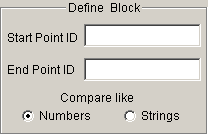
Fill in the
Starting Point ID and
End Point ID then click the ADD from
FILE button.
by Desc
If you choose the
by Desc
method, the following
Specify
Description section will appear below the
Choose Points section of the
dialog.
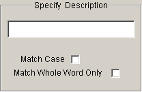
Fill in the description to look for and check
the
Match Case and
Match Whole Work Only
checkboxes as needed. Next click the
ADD from FILE button
and any matching point records will
be added to the list.
by Code
If you choose the
by Desc
method, the following
Specify
Code section will appear below the
Choose Points section of the
dialog. This section of the dialog looks and functions the
same as the
Specify
Description section shown above except you must specify a
code.
by Elev
If you choose the
by Desc
method, the following
Specify
Elevation section will appear below the
Choose Points section of the
dialog.
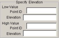
Specify the high and low elevation values.
You can do this by directly entering the elevation values or you
can type a point ID in the
Point
ID edit box then click on another edit box. When you
do this the elevation of the point is written to the appropriate
Elevation edit box.
If you used a point ID to get the elevation, you can edit the value
if necessary. Next click the
ADD from FILE button to add the points
to the list.
in Radius
in Rect
Coordinate File Data Entry
There is only one type of coordinate record called a Point record. This record has six
fields:
Point ID: Point identifier must be
unique. Its format varies according to the type of coordinate
file.
Northing: Specifies the
northing or Y coordinate of a point.
Easting: Specifies the
easting or X coordinate of a point.
Elev: Specifies the
elevation or Z coordinate of a point. (May be On or
Off. To turn the column on click the column
heading.)
Code (C&G coordinate files only):
a 4 character optional field used
to group points. May be blank. (May be On or Off.
To turn the column on click the column heading.)
Description:
Text describing the point.
May be blank. Length limited by type of coordinate
file. (May be On or Off. To turn the column on click
the column heading.)
After adding or
inserting a Point record,
fill in the various fields as needed. Use the Tab or Enter
keys to move from one field to the next. If you press Enter
when in the last activated field in a record, a new blank record
will be created just below the current record and the current field
will be set to the Point ID
field in the new record.
To replace the data in an existing record, just click once on the
field you wish to replace and begin typing the new data. To
edit the data in an existing record, click twice on the field you
wish to edit and make any edits required in the existing data.
Settings Menu
Coordinate Files
Choosing this menu item brings up the Coordinate File Settings
dialog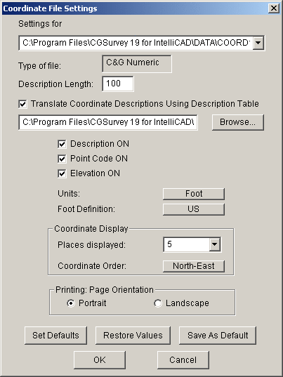
Settings for
drop down list box allows you to
specify settings for any coordinate file currently open in the
CGEditor as well as choose
to set the Default settings for
new files you create.
Type of File is only
visible for the files currently open.
Description Length:
this edit box can be used to set a
new description length for the file. If you choose to change
the description length, any descriptions that already exist in the
file will be truncated to the new length.
Translate Coordinate Descriptions
Using Description Table checkbox
if this is checked then the
description table file name edit box and the Browse... button will be enabled and
you will be required to specify a description table to use.
Description ON checkbox -
if this is checked then the
Description column will be activated in
the editor.
Point Code ON checkbox - if
this is checked then the
Code column will be activated in the
editor. (Only applies to C&G coordinate files)
Elevation ON checkbox - if
this is checked then the
Elevation column will be activated in
the editor.
Units: click the button to
switch between
Foot and
Meter.
Foot Definition:
click the button to switch between
US and
International feet. (Disabled if
Units are set to
Meter)
Coordinate Display
section
Places displayed: drop down list - use
to specify the number of decimal places displayed in the editor for
northing, easting and elevation.
Note: the Places displayed setting does not
affect the values actually stored in the coordinate file, only how
they are displayed in the editor window.
Coordinate Order: click
button to switch between
North-East and
East-North.
Printing: Page Orientation section
choose Portrait or Landscape. You may wish to choose
Landscape to avoid having
the coordinate records with long descriptions causing each page to
span 2 pages in width.
The Set Defaults, Restore Values and Save As Default have been covered
elsewhere.
US Foot menu item
If this menu item is checked units
are US feet. If the Meters menu item is checked, this menu
item is disabled. The check will also be set or cleared by
changes in the Coordinate File
Settings dialog.
International foot menu
item
If this menu item is checked units
are International feet. If the Meters menu item is checked, this menu
item is disabled. The check will also be set or cleared by
changes in the Coordinate File
Settings dialog.
Feet menu item: If this
menu item is checked units are Feet. The check will also be
set or cleared by changes in the Coordinate File Settings dialog.
Meters menu item: If this
menu item is checked units are meters. The check will also be
set or cleared by changes in the Coordinate File Settings dialog.
Note: The settings for US Foot and
International foot will be ignored if Meters is checked.
Tools Menu
With the exception of Renumber
Points, the items on the Tools menu are similar to those
items already described for other file types.
Renumber Points menu
item
When you choose the Renumber
Points menu item you will receive a warning regarding the
problems that may be encountered in existing C&G
drawings.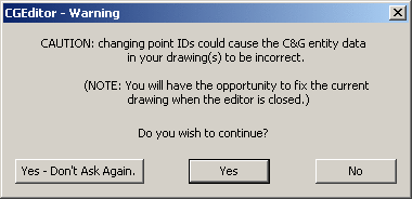 After considering the problems you may
encounter due to point renumbering respond Yes or Yes-Don't Ask Again to continue with
the renumbering operation, or No to cancel the operation.
After considering the problems you may
encounter due to point renumbering respond Yes or Yes-Don't Ask Again to continue with
the renumbering operation, or No to cancel the operation.
If you choose to continue with the renumbering of points, you will
see the Renumber Points
dialog: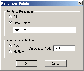 Renumber
Points dialog
Renumber
Points dialog
Points to Renumber section
First choose All or Enter Points.
If you choose Enter Points
you must fill in the edit box specifying the points to
renumber. The points to renumber can consist of single points
or range(s) of points. Multiple entries of ranges and/or
single points must be separated from the next entry by a comma
(",") and ranges must be specified using a dash ("-")
Renumbering Method
section
choose Add or Multiply then enter the Amount to Add: or Multiply by: in the edit box. You
may specify a positive or negative whole number.
When done click
OK.
Click
Cancel to end the
command without changes to the coordinate file being
edited.
Editing C&G Point Group Files
A C&G point group is essentially a list of points placed in a
specially formatted text file (*.pts). It is possible to
create and/or edit point group files using any plain text editor
like Microsoft Notepad or Wordpad if you know the format of the
file. Typically it is far easier to use the CGEditor to
create and/or edit C&G point group files. Point groups
have many uses in C&G commands: road alignments, property
boundaries, define Include
and Exclude Boundaries for
Topo commands, etc.
In the case of alignments, a point group can also include vertical
curve information.
C&G point group files are organized into named subgroups.
The subgroup name can be anything you wish to use to identify the
points that follow. You may have several subgroups in a
single point group file. For example, if you are defining
subdivision lots, then you may choose the subgroup names to be lot
1, lot 2, etc. For an alignment you can make the subgroup
name the starting station and C&G features will make this the
default starting station when asking you for an alignment.
Point groups can also be used to .
Creating and Opening Point Group Files
You may open and/or create as many files as are needed for your
project.
To create a new empty point group file choose the File menu then the New menu item then the Point Group File menu item or, more
simply, just click the "P"
toolbar icon on the Standard toolbar. In either case,
a document window will appear within the main CGEditor
window. This will have a single blank record or row for the
Subgroup name - identified
by SGR in the Type column.
To open an existing point group file, choose File then Open... Then, in the file
dialog, browse to the directory where your point group file is
located, highlight the desired file and click the Open button. The records will be
read from the file and will be displayed in a separate document
window
Entering and Editing Point Group File Data
If you do not have a subgroup name record, choose the Add/Insert main menu then, if you wish
to place it at the end of the file, choose the Add Subgroup menu item or, if you wish
to insert it above the current record, choose the Insert Subgroup menu item. After
filling in the subgroup name, you can just press Enter to add a
single Point record (identified by PNT in the Type column) below the subgroup name
record. Alternatively, you can use the Add/Insert menu to add
or insert a single point or you can choose to add or insert several
points from a coordinate file. These same add and insert
methods can be found on the Add/Insert Toolbar.
If you choose to Add or
Insert Pts from File the
following dialog comes up:
The use of this dialog to choose
points has been described in detail under the section on
Editing Coordinate
Files. Please refer to that section for more
details. After choosing the points you wish to add or insert
into the point group using the C&G Select Points from ... dialog,
click OK and the point records will be created in the point group
file being edited.
Horizontal Curves
You may have noticed that the Rad
Pt Type column is marked with <None> for the points you have
inserted so far. However, if you wish to specify a curve in
your alignment or lot boundary, you must designate the record as a
radius point. If you click on the Cw toolbar icon (for clockwise) or the
Cc toolbar icon (for
counter clockwise) or choose similar items on the Tools menu, you will notice that the
Rad Pt Type column for the
point changes to CW or
CCW to indicate that the
point is a radius point. If a radius point is specified, the
preceding point is assumed to be the PC and the following point is
assumed to be the PT. If you wish to change the point back to
not being a radius point, click the Not Radius Pt toolbar icon or use the
Tools menu.
Vertical Curves
You may enter vertical curve information in a point group
file. This allows you to not only specify the horizontal
location of the alignment, but also its vertical alignment. A
point group file that has vertical curves in it may not contain any
subgroup records. If you attempt to place vertical curve data
in a file having one or more subgroups, you will be given the
following warning: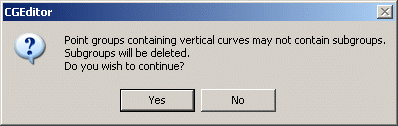 As indicated by the choices in the
dialog, you may continue and place vertical curve info in a point
group file containing subgroups, but it will not be usable in
C&G commands.
As indicated by the choices in the
dialog, you may continue and place vertical curve info in a point
group file containing subgroups, but it will not be usable in
C&G commands.
If you have no subgroups (or if you do and answer "Yes" to the
warning) and this is the first vertical curve in the file, the
Enter Vertical Curve
Information dialog will come up.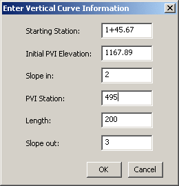 Enter the information in the dialog to specify
the vertical curve. The Starting Station and the PVI Station should be entered as
decimal numbers and when you click in another edit box the decimal
station will be converted to standard station notation. The
Slope in and the
Slope out should be entered
as a percent (For example, enter 2 or 2.0 for 2%). When you
click OK the vertical curve
records VC1 and
VC are added in the
document window.
Enter the information in the dialog to specify
the vertical curve. The Starting Station and the PVI Station should be entered as
decimal numbers and when you click in another edit box the decimal
station will be converted to standard station notation. The
Slope in and the
Slope out should be entered
as a percent (For example, enter 2 or 2.0 for 2%). When you
click OK the vertical curve
records VC1 and
VC are added in the
document window.
For the second and succeeding vertical curves, you can either
Add Vertical Curves to the
end of the vertical curve records or you can Insert Vertical Curves within the
existing vertical curve records. For these vertical curve
records, the dialog requires fewer entries: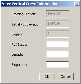 This
is a result of the fact that the initial vertical curve
Starting Station,
Initial PVI Elevation and
Slope in control the
overall vertical orientation of the succeeding vertical curves thus
you need only enter the PVI
Station, Length and
Slope out for these
vertical curves. When you click OK, another vertical curve record will
be added to or inserted into the document.
This
is a result of the fact that the initial vertical curve
Starting Station,
Initial PVI Elevation and
Slope in control the
overall vertical orientation of the succeeding vertical curves thus
you need only enter the PVI
Station, Length and
Slope out for these
vertical curves. When you click OK, another vertical curve record will
be added to or inserted into the document.
Once the vertical curve information has been specified you can go
ahead and enter the points specifying the alignment.
Settings Menu
The Settings menu allows you to configure the point group file and
the record appearance.
Choose the Point Group
Settings menu item to bring up the Point Group Settings dialog: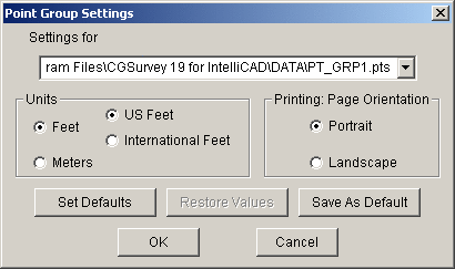 In this dialog you can set the units and
the page orientation for printing.
In this dialog you can set the units and
the page orientation for printing.
Note: the units setting
only effects the display of stations in station notation.
Choose the Record Color
menu item to bring up the Record
Color dialog. Set the display color of the various
records by clicking on the line for the record type. This
brings up a color dialog that allows you to pick from the 16
available colors. Click OK when done.
Tools Menu
The items in the Tools menu
are, for the most part, self-explanatory or have been covered in
detail for other types of files.
Pulldown Menu Location:
CG-Survey>Tools>CGEditor
Keyboard Command:eda,
cg_edit_all
Prerequisite: May need
existing C&G raw traverse data file (*.cgr), C&G Map Check
file (*.cgm), C&G Cross Section file (*.cew), C&G Template
file (*.ctp), coordinate files (*.crd, *.cgc, *.zak, *.mdb) and/or
C&G Point Group files (*.pts)