Combined Transformations
The Combined Transformations feature allows the user to translate,
rotate, adjust elevation and/or scale the selected points in a
specified coordinate file. The user may also specify whether
the transformed coordinates replace the values in the current
coordinate file or are saved to another coordinate file.
The Combined
Transformations menu item brings up the Transform Points dialog box. This
dialog is used to configure the transformations that will be
applied.
To begin the process, in the Coordinate Files Used area, choose the
coordinate file into which the transformed points are to be
stored. If you wish to store them in the current coordinate
file, you can go on to the next step. However, if you wish to
have the transformed points stored to a coordinate file other than
current coordinate file, click the Browse... button and use the file
dialog to choose the desired destination file.
Next, check the checkboxes for each of the transformations you wish
to apply. Then, for each type of transformation to be
applied, fill in each item of data in that area of the dialog.
Translate Points
To translate the points check the Translate checkbox, then fill in the
data in the edit boxes in this section of the dialog.
The amount that the selected points are translated in the North and
East directions is determined by the difference between the
northing and easting of the Reference Point and the coordinates
specified in the New Northing and New Easting edit boxes.
Reference Point specifies
the point in the current coordinate file that is to be used as the
reference point for the translation. All the selected points
are translated in the same manner as the Reference Point. The reference
point will be translated by the difference between its current
coordinates and those specified in the New Northing and New Easting edit boxes. You can
fill in the New Northing
and New Easting edit boxes
directly or you can enter a point ID in the New Point edit box. Assuming the
point ID entered is found in the coordinate file, the coordinates
read from the coordinate file will be placed in the New Northing and New Easting edit boxes. You can
edit these coordinates or leave them as they are.
Rotate Points
If the Rotate check box is
checked, the selected points will be rotated according to the
specifications in the Rotate
Points area. Rotation defaults to rotation by an angle
but can be changed by merely clicking on the Bearing or Angle radio button.
Use the Rotate About Point
edit box to specify the point in the current coordinate file about
which the selected points will be rotated.
Rotating by an angle
To rotate by an angle click the Angle radio button. Next, type in
the appropriate angle in the Rotation Angle edit box or click the
Pick Angle button and pick
the desired angle on the screen.
Rotating by Bearing
To rotate by bearing, click the Bearing radio button then type in the
appropriate values in the Current
Bearing and New
Bearing edit the boxes or click the Pick Bearing button and pick the
desired bearing on the screen.
Note: Bearings must be specified using qdd.mm.sss notation, where q
is the quadrant (1 = NE, 2 = SE, 3 = SW, 4 = NW), dd is degrees, mm
is minutes and sss is seconds. Seconds can be specified to
0.1 seconds if desired.
Adjust Elevation
If the Adjust Elevation box
is checked, the elevations of the points will be adjusted according
to the specifications in the Adjust Elevation area. The type
of elevation adjustment can be specified by clicking on the
Translate or Scale radio button.
To Translate elevations
The elevations of the selected points will be translated by the
difference between the Reference
Point elevation and the value entered in the New Elevation edit box. When you
enter a point ID in the Reference
Point edit box and click on another edit box the
New Elevation edit box will
be filled out with the current elevation of the reference
point.
To Scale elevations
The elevations of the selected points will be scaled by the value
entered in the Multiplication
Factor edit box.
Scale
If the Scale check box is checked the northings and eastings of the
selected points will be scaled according to the specifications in
the Scale area of the dialog.
Meters to Feet and Feet to
Meters
You can scale the coordinates to convert feet to meters or meters
to feet by checking the appropriate check boxes. Using this
form of scaling disables the other items in this section of the
dialog box.
Other types of scaling:
The Point to Hold is a
point in the current coordinate file that will be used to obtain
the reference coordinates for the application of the specified
scaling factor to the selected points.
Simple Scale - if you
choose simple scaling it will calculate the scaled differences in
northing and easting between the Point to Hold and each of the points
selected for scaling. This scaled difference is found
by calculating the difference between the coordinates of the
Point to Hold and those of
a given selected point and multiplying that times the
specified Scale
Factor. This scaled difference is then added back to
the northing (easting) of the given selected point.
Adjust to Grid - this
scaling method uses the Site
Elevation (MSL) and the Projection Table Factor to adjust the
northings and eastings of the selected points to grid
coordinates
Methods of Specifying Point IDs
for the Various Transformations
When specifying a point ID in the transformation data (for example
to specify the Reference
Point when the Translate checkbox is checked), you
many select points using any one of the three options listed
below:
1. Type the point ID directly into the edit box provided.
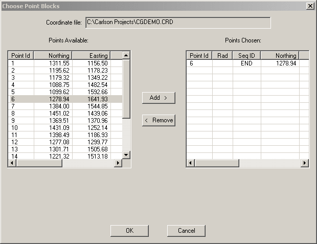
2. Point List: click the Point List button to bring up the
Choose Point Blocks
dialog. The left pane shows a listing of all the points found
in the current coordinate file. Highlight the desired point
in the Points Available
list then click the Add
> button and the point selected will be displayed in the
Points Chosen list.
In every case you are only allowed to choose a single point.
Once you are satisfied with the point chosen click the OK button.
3. Screen Pick: when you click the Screen Pick button the Transform Points dialog disappears and
Choose a point: prompt is
displayed at the command line. You may type a point ID or
pick a point symbol from the drawing.
Selecting Which Points Will be
Transformed
At any time prior to clicking the OK button you may choose the points to
be transformed. To do this click the Select Points button. The
Transform Points dialog will disappear and you will be prompted to
choose the points:
Choose initial points for base
selection set from coord file. (Enter when done)
[All/Block/Code/Desc/Elev/Pt-group/Limits/Radius/Select]:
- use any of the available methods to specify the points to be
transformed. When done specifying the points press Enter
until the Transform Points dialog reappears.
Transforming the points
To transform the selected points, click the OK button. The
points will be transformed and saved to the specified coordinate
file.
Prompts
Fill out the Transform
Points as described above.
When the Select Points button is clicked the following prompt
appears:
Choose initial points for base
selection set from coord file. (Enter when done)
[All/Block/Code/Desc/Elev/Pt-group/Limits/Radius/Select]:
- use any of the available methods to specify the points to be
transformed. When done specifying the points press Enter
until the Transform Points dialog reappears.
Pulldown Menu Location:
CG-Survey > Management > Transformations
Keyboard Command:
cg_transformations
Prerequiste:
Coordinate file