COORDINATE GRID
Choosing the Coordinate Grid item in the CGDraw menu brings up the
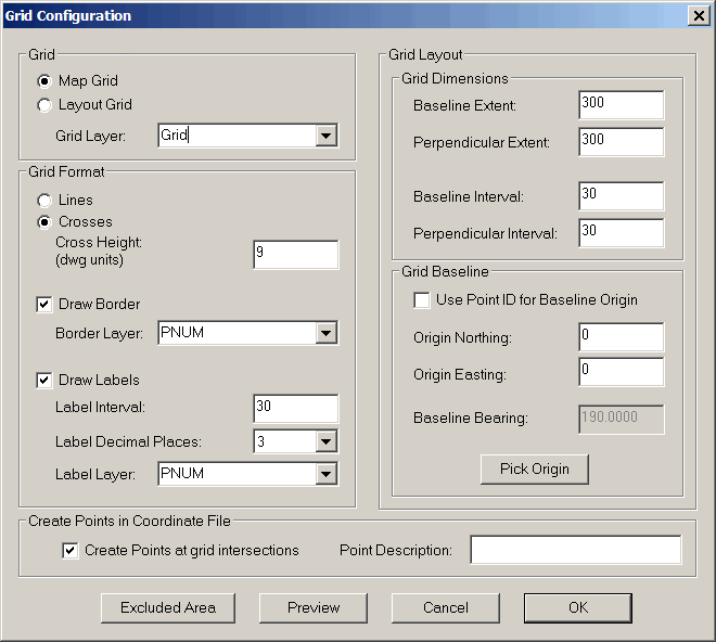
Grid Configuration dialog. The various areas of the dialog
are described below:
Map Grid: is used to
provide a visual reference grid to show northings and eastings on a
map. A Map Grid can be labeled along its border to show the
coordinate values of the grid lines. The Map Grid is oriented
North-South East-West whereas a Layout Grid can be oriented at any
specified bearing.
Layout Grid: is meant to be
used to create points on a regular grid for laying out building
columns, a topo grid, etc. A Layout Grid does not allow for a
border nor for coordinate labels along the border.
Grid Layer: specify the
layer the grid is to be created on. The layer does not need
to exist prior to running this command.
Lines: If selected grid
lines will be drawn for the full height and width of the grid
dimensions.
Crosses: Only crosses will
be drawn at the grid intersections for the full height and width of
the grid dimensions.
Cross Height (drawing
units): this defines the size of the crosses in drawing
units. If your drawing scale is 40 feet and you wish to have
crosses that are 0.25 inches when plotted, you must specify cross
height as 10 feet.
Draw Border: If checked, a
border will be drawn around the perimeter of the defined
grid. You can choose a different layer for the border if you
wish. This will allow you to set the color, line thickness
and/or line type for the border (this option is not available for
Layout Grid).
Draw Labels: Label the grid
lines or crosses around the perimeter at the same interval as the
Baseline and Perpendicular intervals (this option is not available
for Layout Grid) . If checked you must specify:
Label Interval: This number
must be some even multiple of both the baseline and perpendicular
intervals. The Label Interval CAN NOT be less than the base
or perpendicular interval settings.
Label Decimal Places:
Specify the number of decimal places used for the label text.
Label Layer: Specify the
layer the labels are to be drawn on.
Grid Dimensions:
Baseline Extent: This is
the total width of the grid, East to West (or parallel to the
baseline bearing in the case of a Layout Grid).
Perpendicular Extent: This
is the total height of the grid perpendicular to the baseline.
Baseline Interval: This is
the distance between the grid lines (or X’s) drawn perpendicular to
the baseline
Perpendicular Interval:
This is the distance between the grid lines (or X’s) drawn parallel
to the baseline.
Grid Baseline:
Use Point ID for Baseline
Origin: checking this box allows you to use an existing
C&G coordinate for the Grid
Origin. This is typically used for a Layout Grid.
Enter the point ID, or select the point from the screen.
Origin Northing/Origin Easting: manually enter the Northing and
Easting value for the grid origin or pick it on the screen using
the Pick Origin button.
Baseline Bearing: This is
only used when you are drawing a Layout Grid. This is the
bearing of the baseline. Use the standard C&G bearing
input format qdd.mmss (e.g. 125.3527 for N25°35’27”E or 325.5405
for S25E54’04”W)
Pick Origin button: This
option allows you to pick the origin graphically on the
screen. You do not have to pick a C&G point.
Create Points at Grid
Intersections:
Checking this box will cause the default
C&G point to be plotted at each grid point or grid line
intersection and a corresponding point to be stored in the
currently open coordinate file. This is especially useful
when creating a Layout Grid.
Point Description: enter a
point description for the points saved to the coordinate
file.
Exclude Area: This button
allows you to graphically specify a horizontal window within which
no grid is to be drawn. This can be used to guarantee that a
title block, legend or other area is not obscured by the grid or
its labels.
Preview: This button allows
you to preview the grid as specified. Pressing <Enter>
will return you to the Grid Configuration dialog allowing you to
make changes if necessary.
Cancel : This button exits
the command without drawing the grid.
OK: This button causes the
grid to be drawn.
Pulldown Menu Location:
CG-Survey > CGDraw>Coordinate Grid
Keyboard Command: GRD,
CG_DRAW_GRID
Prerequiste:
Coordinate file