Pipe Connector
This command draws the geometry of the connector pipe between
two points in the current drawing, and outputs the connector pipe
geometry to an IFC file.
Set Flange 1 & 2:
Allows you to select groups of points representing the first and
second (start and end) points to be connected. Groups of points are
expected to be laid out in a pattern resembling a circle. The best
estimate of the center of this group of points will be the first or
second connection point respectively1. Using Set Flange
1 or 2 will also set flange direction 1 and 2 such that the first
point is "facing" the second point and the second point is "facing"
the first point.
Flange 1 & 2 Position:
Position of the first and second point that the connector pipe will
join.
Flange 1 & 2 Direction:
Direction from which the beginning and end of the connector pipe
will emanate.
Elbow 1 Radius:
Radius of the 1st elbow in the connector pipe geometry. This will
be -1 if no pipe geometry is feasible2.
Elbow 2 Radius:
Radius of the 2nd elbow in the connector pipe geometry. This will
be -1 if only 1 elbow is needed to connect the start and end points
of the connector pipe, or if no pipe geometry is
feasible2.
Pipe Diameter:
Diameter of connector pipe2.
Pipe Thickness:
Thickness of the connector pipe2.
Output IFC Path:
Output file path for the IFC file. Can be set using the "Select"
button.
1. Pipe Connector performs various
calculations when determining the geometry of the connector pipe.
Because of this, the actual point that is determined by Set Flange
1 & 2 may not be the center of the group of points selected by
the user. For example, if the two points can be joined by a pipe
with only one elbow if one of the points is altered "slightly"
Pipe Connector will alter the two points to
simplify the pipe connector geometry in this way.
2. The feasibility of the connector pipe geometry depends on
many variables. The two most common:
A) set flange 1 and 2 will attempt to set the the direction
of the first and second point such that they face each other.
However as the direction is editable, it is possible to set the
point and direction of the first and second points of the connector
geometry that cannot be connected.
B) Given a pipe Diameter and thickness it may be impossible
to curve a pipe such that it connects the first point of the
connector pipe to the second point of the connector point. If a
larger radius is feasible, Pipe Connector will automatically
compute this value, otherwise radius 1 and 2 will be set to
-1.
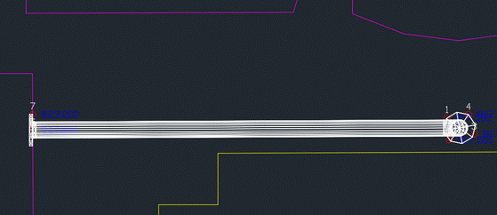
Example
In this drawing the points (1, 2, 3, 4) and (5, 6, 7)
will be used to specify the start and end point of the connector
pipe. After being selected by Set Flange 1 and Set Flange 2
respectively and pressing okay, an ifc file will be written to the
output IFC path and the connector geometry will be drawn in the
drawing "demo3." (see below).
Pulldown Menu Location: BIM
Keyboard Command:
pipe_connector
Prerequisite: Points on connections