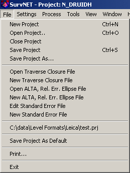
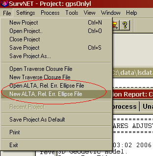
Selecting the File menu opens the following menu:
A Project (.PRJ) file is used to store all the settings and files necessary to reprocess the data making up the project. You can create a New project, or Open an existing project. It is necessary to have a project open in order to process the data.
The Save Project As Default can be used to
create default project settings to be used when creating a new
project. The current project settings are saved and will be used as
the default settings when any new project is created. Project
settings are covered in the Settings menu sections.
Some statutes and jurisdictions still require the computation of traditional traverse closures. SurvNet gives the surveyor the ability to compute the closures of multiple traverses within a project as part of the preprocessing of the project raw data. Closures for single or multiple traverses can be computed for a single project. Additionally, GPS closures can be computed for GPS loops. To compute closures you must first create a "Closure" file (.CLS). Closure files define the type of traverse loops that are to be computed and the point numbers that make up the traverse.
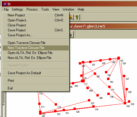
There are two options in the FILE menu that are used to create and edit the closure, .cls, files:
Open Traverse Closure File
New Traverse Closure File
First enter the point sequence which
defines the traverse in the 'Ordered Traverse Point List' grid
field. If you initiate the traverse closure input dialog from the
FILE menu (as opposed to running it from the Settings Dialog), you
will have the option to pick the points graphically.
Set the check boxes to set whether vertical closure and angle closures are to be computed. Then choose what type traverse is being entered. .
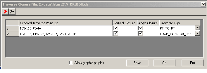
Enter the points that define the traverse. If you check the
"Allow graphic pt. pick" box, the graphic window will pop up. You
can then pick the points graphically. The points will go into the
list separated by commas.
If you manually enter the points, they can be entered in the form:
1,23,30-35,45,23,1
A comma separates the point numbers. You can select a range (30-35)
when the points are sequential. You must start with the first
backsight point number and end with the last foresight point
number. For example, if you have a simple loop traverse with angle
closure using points 1, 2, 3 and 4, it will be entered as
"4,1,2,3,4,1" where 1 is the first occupied point and 4 is the
initial backsight.
You can turn the "Angle Closure" ON or OFF. If the angle closure is
ON, you will be shown the total angular error and error per angle
point. If the final closing angle was not collected you can turn
"Angle Closure" OFF and only the linear closure will be
computed.
You can turn the "Vertical Closure" ON or OFF. If the vertical
closure is ON, you will be shown the total vertical distance
closure.
In order to calculate the traverse closure, you must select the
TRAVERSE TYPE. It can be:
Pt. to Pt. Trav. - A point to point traverse is a traverse
that starts at a set of known coordinates and ends at another known
coordinate. This option assumes you start from two control points
and tie into two control points if an angle closure is desired and
one control point if only a linear closure is desired. The first
backsight distance and last foresight distance if angle closure is
ON are not used in computing the linear closure. Following is an
example of a pt. to pt. traverse with angle closure.
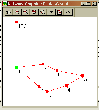
100,101,2-5
In the above pt. to pt. list Pt 100 is the starting backsight point, Pt. 101 is the starting instrument point. Pt. 4 is the ending instrument point and the foresight to the angle closure point is point 5. If a closing angle was not collected the list would look as follows '100,101,2-4'.
Loop Trav., Int. Az. Ref. - A closed loop traverse that begins by backsighting the last interior point on the traverse. Following is an example.
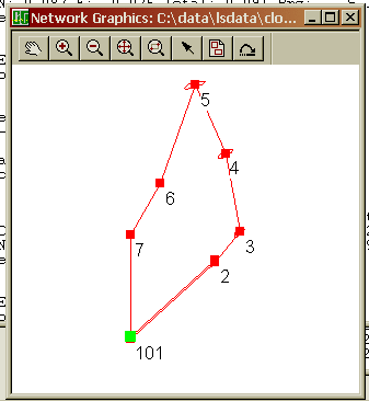
7,101,2-7,101
In the above example closed loop with angle balance list, point 7 is the backsight point and point 101 is the first occupied point. If the closing angle 6-7-101 was not collected the list would be entered as follows ' 7,101,2-7'
Loop Trav., Ext. Az. Ref. - A closed loop traverse that begins by backsighting an exterior point (point not on the traverse).
100,101,2-7,101,100
In the above example loop with exterior reference and angle balance list, point 100 is the backsight point and point 101 is the first occupied point. If the closing angle 7-101-101 was not collected the list would be entered as follows ' 100,101,2-7,101'
GPS Loop Closure: - GPS loop closures can be computed using this option.
A,E,F,A
In the above example GPS loop, closure will be computed from the
GPS loop going from A-E-F-A.
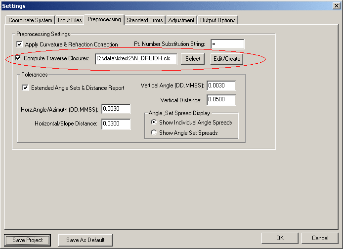
After the closure, .CLS, file has been created the preprocessing project settings need to be updated to include the closure file in the project. Following is a view of the settings screen that defines a closure file to be used in preprocessing. Notice that the check box 'Compute Traverse Closure' is checked and a closure file has been entered in the edit box field. Notice that the 'Edit/Create' button can be used to edit an existing closure file or create a new closure file.
When the data is processed, the closure reports will appear in the RPT and ERR files. Traverse Closures will show the error of closure with and without angles balanced. Following is an example of a closed loop traverse report:
Traverse Closures
=================
Traverse points:
103-118,43-44
Traverse starting and ending on different points;
Compute angle closure.
Compute vertical closure.
BS IP FS Angle FS H. Dist. FS V. Dist.
103 104 105 173-07'48.5" 310.4916 -7.7483
104 105 106 167-48'21.5" 253.4909 5.6306
105 106 107 200-52'46.0" 381.4896 8.4879
106 107 108 149-09'05.5" 410.5470 -16.6830
107 108 109 080-42'36.5" 245.5728 9.4221
108 109 110 174-21'17.5" 175.3846 -5.6971
109 110 111 201-42'21.5" 367.0014 -11.8161
110 111 112 171-52'54.5" 237.7806 7.5346
111 112 113 192-32'53.5" 368.8396 -7.0329
112 113 114 171-30'59.0" 338.0024 -19.1945
113 114 115 184-54'03.5" 344.5005 16.3157
114 115 116 149-20'19.5" 353.8455 7.5562
115 116 117 202-19'01.5" 390.1117 -9.9180
116 117 118 112-36'32.0" 293.9931 2.0060
117 118 43 146-06'36.5" 411.3674 -7.7112
118 43 44 270-04'01.5"
Closing Az: S 47-39'47.8"W
Computed Closing Az: S 47-39'51.3"W
Total angular error: 000-00'03.5"
Angular error per point: 000-00'00.2"
Correct Ending Coordinates, North: 1400952.0140 East: 2241884.7010
Ending Coordinates, North: 1400951.7962 East: 2241884.8180
Error, N: -0.2178 E: 0.1170 Total: 0.2472 Brg: N 28-14'34.6"W
Distance Traversed: 4882.4190 Closure: 1:19751
Correct Ending Elevation: 948.1710
Ending Elevation: 948.1221
Elevation Error: -0.0489
Closure After Angle Adjustment
103 104 105 173-07'48.3" 310.4916 -7.7483
104 105 106 167-48'21.3" 253.4909 5.6306
105 106 107 200-52'45.8" 381.4896 8.4879
106 107 108 149-09'05.3" 410.5470 -16.6830
107 108 109 080-42'36.3" 245.5728 9.4221
108 109 110 174-21'17.3" 175.3846 -5.6971
109 110 111 201-42'21.3" 367.0014 -11.8161
110 111 112 171-52'54.3" 237.7806 7.5346
111 112 113 192-32'53.3" 368.8396 -7.0329
112 113 114 171-30'58.8" 338.0024 -19.1945
113 114 115 184-54'03.3" 344.5005 16.3157
114 115 116 149-20'19.3" 353.8455 7.5562
115 116 117 202-19'01.3" 390.1117 -9.9180
116 117 118 112-36'31.8" 293.9931 2.0060
117 118 43 146-06'36.3" 411.3674 -7.7112
118 43 44 270-04'01.3"
Closing Az: S 47-39'47.8"W
Computed Closing Az: S 47-39'47.5"W
Total angular error: 000-00'00.2"
Angular error per point: 000-00'00.0"
Correct Ending Coordinates, North: 1400952.0140 East: 2241884.7010
Ending Coordinates, North: 1400951.7752 East: 2241884.8397
Error, N: -0.2388 E: 0.1387 Total: 0.2762 Brg: N 30-08'45.6"W
Distance Traversed: 4882.4190 Closure: 1:17679
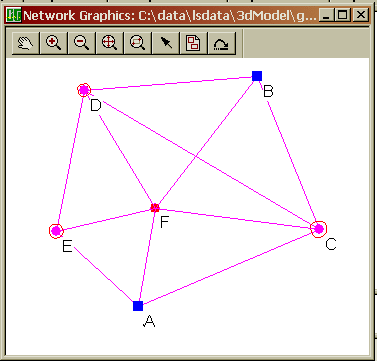
Following is an example of a GPS loop closure report.
Traverse Closures

=================


GPS Loop Points:

A,E,F,A


GPS Loop Closure;

  Misclosure, X:  -0.0323   Y:  -0.0162   Z:  -0.0105

  Closure error:    0.0376   Perimeter: 20229.3858

  Precision: 1:537594


GPS Loop Points:

C,F,D,B,C


GPS Loop Closure;

  Misclosure, X:  -0.0121   Y:  -0.0101   Z:   0.0002

  Closure error:    0.0158   Perimeter: 41332.9807

  Precision: 1:2622216


GPS Loop Points:

F,D,B,F


GPS Loop Closure;


  Misclosure, X:  -0.0022   Y:  -0.0044   Z:   0.0097

  Closure error:    0.0109   Perimeter: 30814.5047

  Precision: 1:2833226
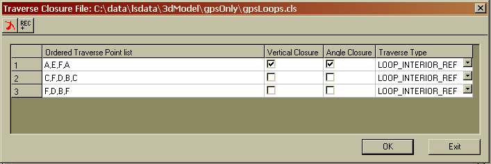
Following is a view of the closure file that created the above GPS closure report. The 'Vert. Closure', and 'Angle Closure' toggles serve no purpose with GPS loop closures.
SurvNet provides the ability to generate reports that give the
surveyor the information needed to determine if his survey is
within ALTA positional tolerances. It is required that the user
define which points are to be included in the ALTA testing. The
points to be included for ALTA testing are defined in an .Alt
file.
There are two options in the FILE menu that are used to create and
edit the ALTA, .alt, files:
Open ALTA, Rel. Err. Ellipse File
New ALTA, Rel. Err. Ellipse File
After choosing the ALTA file to be created or edited the following dialog box is displayed.
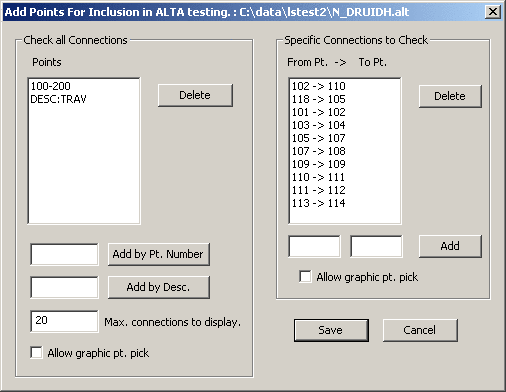
All the ALTA reporting settings reside within the Relative Error Ellipse box.
Note: You do not have to "Enable sideshots for relative error ellipses" to get an ALTA report on sideshots that are selected for the report. All points selected for the ALTA report will automatically be included in the computational process.
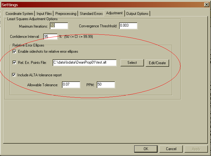
The 'Rel. Err. Points File:' check box must be checked, and an .ALT file must be chosen to get an ALTA report. The .ALT file defines which points will be included in the ALTA reporting. See the previous discussion on the creation of the .ALT file if you are unsure of how to create an .ALT file.
Check the 'Include ALTA tolerance report' check box to create the ALTA tolerance checking report section. If an .ALT file has been chosen then the relative error section of the report will always be generated.
Next make sure the appropriate
tolerance and PPM has been defined. The ALTA standards define their
positional standard as .07 plus 50 PPM. Additionally, the
ALTA standards require that the computations be performed to a 95%
confidence. The confidence interval is set in the 'Confidence
Interval:' edit field.
After the project has been processed
the ALTA/Relative Error portion of the report is displayed in the
report window under its own tab.
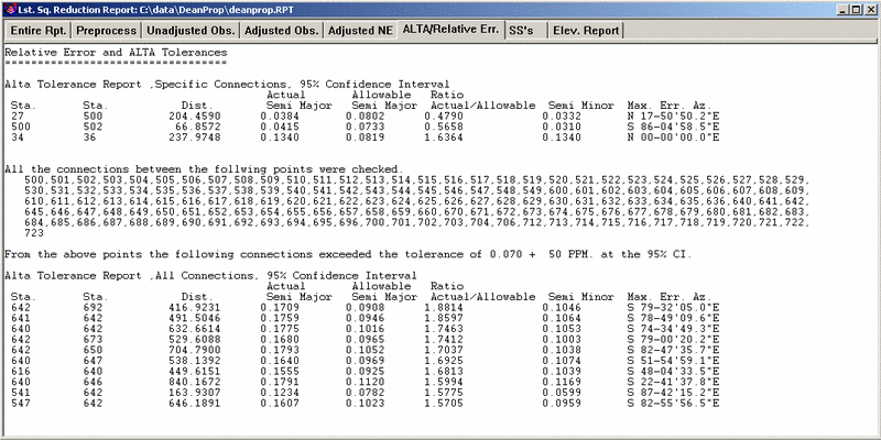
Relative Error and ALTA TolerancesIf the Ratio Actual/Allowable is 1.0 or less, the positional tolerance of the two points have passed the ALTA standards.
==================================
Alta Tolerance Report ,Specific Connections, 95% Confidence Interval
Actual Allowable Ratio
Sta. Sta. Dist. Semi Major Semi Major Actual/Allowable Semi Minor Max. Err. Az.
27 500 204.4590 0.0384 0.0802 0.4790 0.0332 N 17-50'50.2"E
500 502 66.8572 0.0415 0.0733 0.5658 0.0310 S 86-04'58.5"E
34 36 237.9748 0.1340 0.0819 1.6364 0.1340 N 00-00'00.0"E
All the connections between the following points were checked.
500,501,502,503,504,505,506,507,508,509,510,511,512,513,514,515,516,517,518,519,520,521,522,523,524,525,526,527,528,529,
530,531,532,533,534,535,536,537,538,539,540,541,542,543,544,545,546,547,548,549,600,601,602,603,604,605,606,607,608,609,
610,611,612,613,614,615,616,617,618,619,620,621,622,623,624,625,626,627,628,629,630,631,632,633,634,635,636,640,641,642,
645,646,647,648,649,650,651,652,653,654,655,656,657,658,659,660,670,671,672,673,674,675,676,677,678,679,680,681,682,683,
684,685,686,687,688,689,690,691,692,693,694,695,696,700,701,702,703,704,706,712,713,714,715,716,717,718,719,720,721,722,
723
From the above points the following connections exceeded the tolerance of 0.070 + 50 PPM. at the 95% CI.
Alta Tolerance Report ,All Connections, 95% Confidence Interval
Actual Allowable Ratio
Sta. Sta. Dist. Semi Major Semi Major Actual/Allowable Semi Minor Max. Err. Az.
642 692 416.9231 0.1709 0.0908 1.8814 0.1046 S 79-32'05.0"E
641 642 491.5046 0.1759 0.0946 1.8597 0.1064 S 78-49'09.6"E
640 642 632.6614 0.1775 0.1016 1.7463 0.1053 S 74-34'49.3"E
642 673 529.6088 0.1680 0.0965 1.7412 0.1003 S 79-00'20.2"E
642 650 704.7900 0.1793 0.1052 1.7037 0.1038 S 82-47'35.7"E
640 647 538.1392 0.1640 0.0969 1.6925 0.1074 S 51-54'59.1"E
616 640 449.6151 0.1555 0.0925 1.6813 0.1039 S 48-04'33.5"E
640 646 840.1672 0.1791 0.1120 1.5994 0.1169 S 22-41'37.8"E
541 642 163.9307 0.1234 0.0782 1.5775 0.0599 S 87-42'15.2"E
547 642 646.1891 0.1607 0.1023 1.5705 0.0959 S 82-55'56.5"E