|
| Dialog if using an existing .MXS file |
This command will create or append to a section alignment file
which is stored as a Multiple Cross Sections (.MXS) file. This file
contains the coordinates that define the center and endpoints of
section lines and is a requirement of many section commands such as
Sections from Surface Entities and Sections to 3D
Polyline. The section alignment defines the stations along a
centerline and how far left and right to create cross sections.
This routine starts by asking for a new or existing .MXS file name.
Then the centerline is specified by either by choosing a centerline
file (.CL file) or selecting a polyline that represents the
centerline. Next, the program prompts for the starting station of
the centerline. If this is a new section alignment, the Make MXS
File Settings dialog appears.
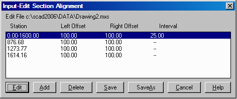
The Input-Edit Section Alignment dialog lists all the section stations and offsets in the alignment of an existing .MXS file.
|
|
| Dialog if using an existing .MXS file |
Edit: Allows you to edit the currently highlighted
row.
Add: Allows you to add more sections by displaying the Make
MXS File Settings dialog (shown below).
Delete: Deletes the currently highlighted row.
Save: Saves the MXS file, exits this dialog and draws the
section alignment on the screen using temporary vectors (yellow for
left offsets, magenta for right offsets). Any viewport change such
as Redraw or Zoom will cause these vectors to
disappear. The draw the section lines with Line entities, use the
Draw Section Alignment command.
SaveAs: Saves a new MXS file with a user-specified
name.
|
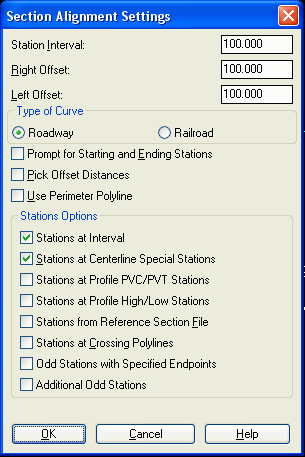
| Dialog used for a new section alignment |
Station Interval: Enter the station interval for
sections.
Right Offset: Enter the width for the sections, right of the
centerline. Not available if Pick Offset Distances is checked.
Left Offset: Enter the width for the sections, left of the
centerline. Not available if Pick Offset Distances is checked.
Type of Curve: Specify either Roadway or Railroad curve to
account for the differences in stationing curves.
Prompt for Starting and Ending Stations: This option allows
you to specify the range of stations to process. Otherwise the
program will use the full station range of the centerline.
Pick Offset Distances: Allows you to specify the offsets by
using the distance between two picked points in the drawing.
Use Perimeter Polyline: Allows you to specify a closed
polyline that will be used as the limit of the cross sections. The
offsets will be contained within this closed polyline.
Stations at Interval: Creates cross sections at the
specified interval such as every 25 feet. If the Prompt for
Starting and Ending Stations is on, then the program will apply the
station interval to the user-specified range of stations. Otherwise
the station interval is used along the entire centerline.
Stations at Centerline Special Stations: Creates cross
sections at every transition point in the centerline such as the
PC, PT, spiral points and end points.
Stations at Profile PVC/PVT Stations: Creates cross sections
at profile vertical curve transitions stations. When active, the
program will prompt for the profile to process.
Stations at Profile High/Low Stations: Creates cross
sections at profile vertical curve high and/or low stations. When
active, the program will prompt for the profile to process.
Stations from Reference Section File: Creates cross sections
at stations contained in the reference section file. When active,
the program will prompt for the section file to process.
Stations at Crossing Polylines: Allows you to select
polylines that cross the centerline and creates cross sections at
the intersections of these polylines with the centerline.
Sections from Polyline: This method prompts to select
polylines that define the section alignments. This method is handy
when the section alignments have multiple bends such as for
HEC-RAS.
Stations at Crossing Pipes: This method creates cross sections
at the stations where pipes intersect.
Odd Stations with Specified Endpoints: Creates cross sections
at stations that are entered or at picked points along the
centerline. This option also allows you to pick the left and right
offset points which do not have to be perpendicular to the
centerline.
Additional Odd Stations: Creates cross sections at the
specified stations but the offsets are always perpendicular to the
centerline with the user-defined default offset distances.
Use Exclusion Areas:
This option prompts for selecting closed polylines to use as
exclusion areas which are areas to skip for the section surface.
The stations and offsets for the exclusion areas are stored in the
section alignment file. Then routines like Calculate Section
Volumes and Draw Sections will skip over these areas and not
calculate volumes or draw section lines in these areas.
Allow Sections Overlap: On the inside of a centerline curve,
section lines will cross when the section length is longer than the
radius. This option controls whether to shorten the section lines
on the inside of the curve or to keep the regular length and let
the section lines cross.
Specify an MXS file dialog Choose new or existing.
Polyline should have been drawn in
direction of increasing stations.
CL File/<Select polyline that
represents centerline>: pick centerline
Enter Beginning Station of
Alignment <0.00>: press Enter
Pulldown Menu Location: Sections
Keyboard Command: editmxs
Prerequisite: A polyline centerline or a centerline .CL
file