Vehicle Path Tracking
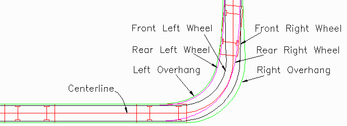
This command traces the wheel paths
for vehicle dimensions along a centerline. The centerline is
defined by a polyline which must be created before running this
command. The center of the front axis follows this centerline.
After specifying the vehicle dimensions and draw options in the
command dialog, the program prompts for the centerline polyline and
then draws the paths.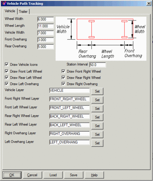 Wheel
Width: Distance along the wheel axis to the outside of the
tires.
Wheel
Width: Distance along the wheel axis to the outside of the
tires.
Wheel Length: Distance between the front axis and rear
axis.
Vehicle Width: Outside width dimension of the vehicle
body.
Front Overhang: Distance from front axis to front of vehicle
body.
Rear Overhang: Distance from rear axis to the back of the
vehicle body.
Draw Vehicle Icons: Draws the vehicle symbol with the
vehicle dimensions on the Vehicle
Layer. Draw Method chooses between placing vehicle
icons at the specified Station
Interval along the centerline or prompting to pick points
along the centerline to place the vehicle icons.
The Save and Load buttons save and recall the
vehicle dimensions to a .VTP file.
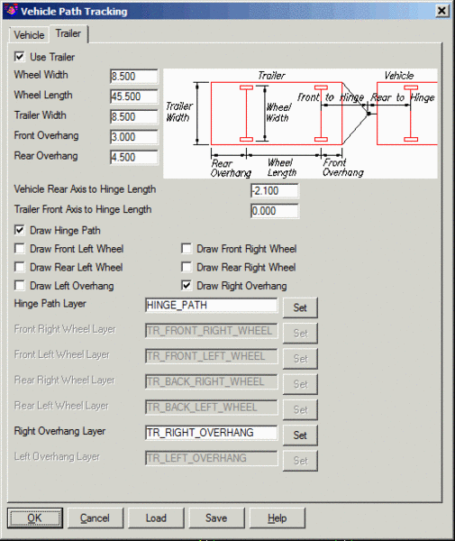
For hinged vehicles, pick on the Trailer Tab and turn on the Use
Trailer toggle. There is a separate set of dimensions for the
trailer and separate layers for the trailer points to track.
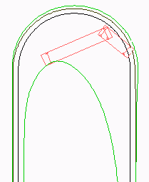
Trailer settings
and results for Interstate Semitrailer
Prompts
Vehicle Path Tracking
dialog
Select centerline polyline:
pick a polyline
Pulldown Menu Location: Roads
Keyboard Command: auto_track
Prerequisite: Centerline polyline