Road Network
This command synthesizes road network design for subdivisions and
commercial and industrial sites by enabling interactive 3D design
of all road centerlines, profiles and templates, including
cul-de-sacs. A docked dialog on the left of the screen identifying
the existing DTM surface and all road files combines with an active
CAD screen and command line. You can save drawings and run
virtually any standard Autocad command while within the docked
dialog. Once the user identifies all centerlines involved,
the program detects intersections and end segments suitable for
cul-de-sacs, and through user input of design parameters for
cul-de-sac dimensions and intersection transitions, the program
will process the complete 3D design, with output options including
cross sections, 3D faces, TIN files and contours. The many
roading files involved in a road network design are all saved to an
"RDN" file that can be recalled, modified and re-processed.
This Road Network Help document is divided into 7
parts: Road Network Task
Pane, Road
Network Settings, Adding and Editing
Roads, Road Network Road Profile
Editor, Adding and Editing
Intersections, Adding and Editing Cul de
Sacs, Road
Network Workflow Example #1 and Road network Workflow Example
#2
Road Network: Task Pane
When designing roads using Carlson's Road Network
feature, all work is done through a Task Pane that
docks along the left side of the drawing screen. Having the
Task Pane open and active does not prohibit or
interfere with normal Command: line or other CAD functionality.
All settings and files associated with a roadway design project are
saved in the Road Network (.RDN) file. Upon starting the
Road Network command, the user is prompted to open
an existing or create a new Road Network (.RDN) file in which to
save the project data. Once loaded, the active Road Network
filename is displayed at the top of the Task
Pane.
Once Roads, Intersections and Cul-de-Sacs have been added to the
Road Network, selecting any one of them in the project tree
highlights the feature and centers it in the drawing screen.
Highlighting and centering options may be changed in the Display Options tab
of the Road Network
Settings dialog box.
Road Network Task
Pane
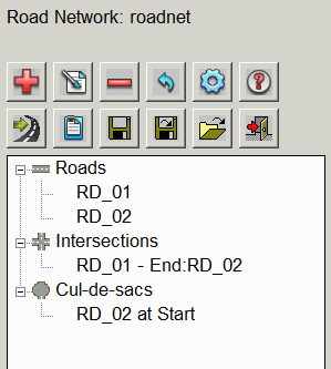
Roads
This area of the project tree lists the Roads defined as part of
the Road Network. See Road
Network: Adding and Editing Roads for additional
assistance. The functions are accessed by right-click on the tree
or by the icon buttons at the top of the dialog
Add: Pick this button to Add a Road to the
Network. After adding the Road, the Edit Road dialog box
is displayed allowing the user to manage and make changes to the
Input Files and
Output Files for
the selected Road.
Edit: Pick this button to display the Edit Road dialog box
to manage and make changes to the Input Files and Output Files for the
selected Road.
Remove: Pick this button to delete the selected
Road from the Road Network. After Removing the Road from the
Network the design files associated with that Road will remain in
the project folder.
Intersections
This area of the project tree lists the Intersections within the
Road Network. Intersections are created automatically as
intersecting Roads are added to the Network. See Road Network: Adding and
Editing Intersections for additional assistance.
Edit: Use this button to display the Edit Intersection dialog
box and make changes to the Input Data and
Output
Files for the selected Intersection. Other changes
that can be made to the Intersection design are:
1) Changing the Primary/Secondary status of the Roads creating the
Intersection,
2) Making design changes that apply to the entire Intersection,
3) Making design changes that apply to one or more Corners of the
Intersection.
Reset: Use this button to overwrite all design
changes made to the selected Intersection and reset to the original
Intersection design.
Cul-de-Sacs
This area of the project tree lists the Cul-de-Sacs defined as part
of the Road Network. See Road Network: Adding and Editing
Cul-de-Sacs for additional assistance.
Add: Picking this button will display a list of
Roads in the Network and prompt the user to "Select Road
for Cul-de-Sac".... After selecting the Road, the
Edit Cul-de-Sac dialog box is displayed allowing
the user to specify the Input
Data and Output
Files for the Cul-de-Sac.
Edit: Use this button to display the Edit
Cul-de-Sac dialog box and make changes to the input data and output files for the
selected Cul-de-Sac.
Remove: Use this button to Remove
the selected Cul-de-Sac from the Road.
Task Pane Buttons
 Process:
 Use this button to manually
trigger the computation process for the Road Network and perform
the tasks configured in the
Output Options tab of
the
Road Network
Settings dialog box.
 Report: Use this
button to Save or Print one of two Reports provided by the
Road Network feature which are: the
Output Processing report and the
Input Data Files report. Default Report
settings can be changed in the Report Options tab of
the Road Network
Settings dialog box.
Report: Use this
button to Save or Print one of two Reports provided by the
Road Network feature which are: the
Output Processing report and the
Input Data Files report. Default Report
settings can be changed in the Report Options tab of
the Road Network
Settings dialog box.
The Output Processing Report displays the
cut/fill and material quantities for each Road, Intersection and
Cul-de-Sac of the Road Network.
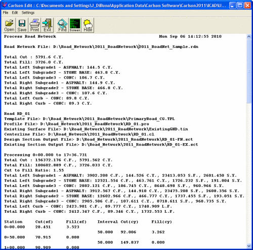 Road Network Output Processing
Report
Road Network Output Processing
Report
The Input Data Files Report displays all
of the user-specified design files associated with the Road
Network. The user has the option of reporting only the filename or
both the path and filename.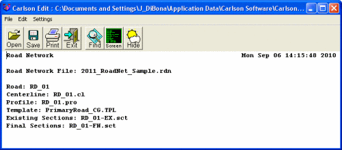
Road Network Input Data
Files Report
 Settings: This button displays the Road Network Settings
dialog box which is the starting place for all projects designed
using the Road Network feature. There are 5 tabs
in the dialog box: Process
Options, Output
Options, Report
Options, Display
Options and Transition
Defaults.
Settings: This button displays the Road Network Settings
dialog box which is the starting place for all projects designed
using the Road Network feature. There are 5 tabs
in the dialog box: Process
Options, Output
Options, Report
Options, Display
Options and Transition
Defaults.
Save: Pick this button to Save
the Road Network (.RDN) file.
SaveAs: Pick this button to Save the current Road
Network (.RDN) file and give it a new path and/or filename.
Load/New: Pick this button to
Load an existing or start a New
Road Network (.RDN) file.
Exit: Pick this button to Exit
the Road Network command and close the Task
Pane.
Road Network: Settings
The Road Network Settings dialog box is accessible
from the Settings button on the Road Network: Task Pane.
The Road Network Settings dialog box is the
starting place for all projects designed using the Road
Network feature. There are 5 tabs in the dialog box:
Process
Options, Output
Options, Report
Options, Display
Options and Transition
Defaults.
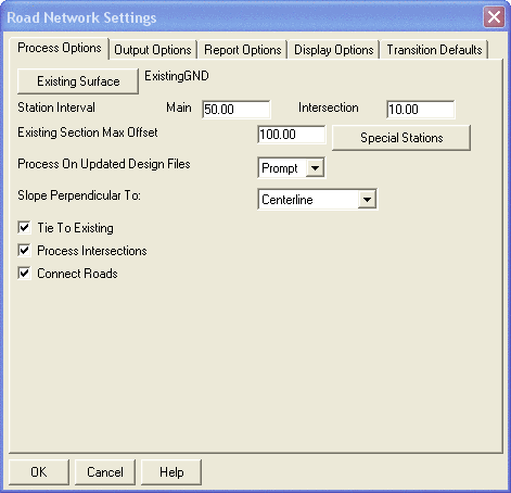
Process Options
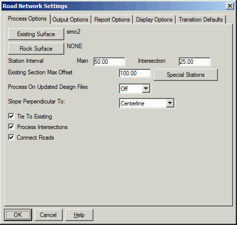 Process Options Tab
Existing Surface: Use this button to browse to and
select the Existing Surface file to be used for the Road Network.
Either a TIN or FLT triangulation file are accepted as valid
surfaces, both of which can be made within the command Triangulate
and Contour. For speed, it is recommended that the binary TIN
file format be selected.
Rock Surface: Use this button to set the Rock
Surface file to be used for the Road Network. This Rock Surface is
optional. When the Rock surface is specified, the program will
report rock quantities with the cut. Also, the cut definition in
the road template file can have a separate slope to the rock
surface.
Station Interval: These settings determine the
distance between cross-section samples. The user has the option of
specifying one sampling interval for the Intersection and another
for the remainder of the Road.
Existing Section Max Offset: Use this setting to
specify the furthest distance left and right of the Centerline that
cross-sections are to be sampled.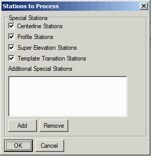 Special Stations: This button
displays the Stations to Process dialog box (shown
above). This box allows the user to decide whether or not
cross-sections are to be sampled at critical design points along
each Centerline. Special Stations include critical
points such as the PC & PT for Centerlines and the PVC, PVT,
High Point and Low Point for Profiles. "Additional Special
Stations" may be added by entering the station number. These
settings apply to all Roads in the Road
Network. To identify Special Stations for a
particular Road, pick the Special Stations button
in the Edit
Road dialog box.
Special Stations: This button
displays the Stations to Process dialog box (shown
above). This box allows the user to decide whether or not
cross-sections are to be sampled at critical design points along
each Centerline. Special Stations include critical
points such as the PC & PT for Centerlines and the PVC, PVT,
High Point and Low Point for Profiles. "Additional Special
Stations" may be added by entering the station number. These
settings apply to all Roads in the Road
Network. To identify Special Stations for a
particular Road, pick the Special Stations button
in the Edit
Road dialog box.
Process On Updated Design Files: This setting has
3 options: Off,
Prompt and
Auto:
Off: This option allows
changes to the design files without triggering an automatic update
to the entire Road Network.
Prompt: This option
automatically prompts the user, "Process Road
Network?" when design files are changed.
Auto: This option
automatically updates the Road Network any time a design file is
changed.
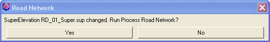 Prompt to Process Updated Road
Network Design
Prompt to Process Updated Road
Network Design
Slope Perpendicular To: This setting allows the
user to specify the direction of cut and fill slope projection by
selecting one of two options: Centerline
and Slope Direction. The
Centerline method projects the cut and
fill slopes perpendicular to the Centerline of the Road without
regard to the Profile of the Road. The Slope
Direction method considers the Profile of the Road
when projecting the specified cut and fill slopes. For example,
projecting cut and fill slopes of 2:1, perpendicular to the
Centerline, along a length of Road with a Profile slope of 10%
would result in a slightly steeper slope (1.96:1) if measured along
the top or toe of that slope. If the same conditions exist but the
Slope Direction method is applied, the
resulting slope (when measured perpendicular to the Centerline) is
slightly less steep (2.04:1) but when measured along the top or toe
of slope will be exactly 2:1.
Tie to Existing: If enabled and cut and fill
slopes have been defined in the Template (.TPL) file, this setting
will project the specified slopes to the Existing Ground surface.
If not enabled, the Road design will stop at the last Template ID preceding the
cut and fill slopes.
Process Intersections: If enabled this option will
calculate all Roads and Intersections. If it is not enabled, each
Road will be processed individually.
Connect Roads: This option applies to the 3D
polylines/breaklines that are created when Processing the Road
Network. If this option is enabled, the 3D polylines for different
Roads will be combined around and through Intersections. If it is
not enabled, the polylines will be drawn for each Road
separately.
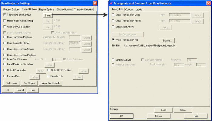
Output Options
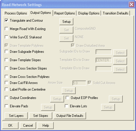 Output Options Tab
Triangulate and Contour: When enabled, use the
Setup button to display the Triangulate
and Contour From Road Network dialog box. Since this
command is very similar to the Surfaces → Triangulate and
Contour command, only those Settings and Options directly
affecting the Road Network will be discussed here. Please refer to
the Help files for that command if additional
assistance is needed.
In the Triangulate and Contour From Road Network dialog
box...
Triangulate tab
Draw Triangulation Faces: The
Road Network version of this command provides
additional controls (beyond those in the standard
Triangulate and Contour command) for managing the
color of the "Triangulation Faces". Once the "Triangulation Faces"
option is enabled, the Set Colors/Layers button
becomes active and, when picked, will display the Road
Color Settings dialog box (shown below). The color of the
faces can be set either by using the Template IDs defined in
the Template (.TPL) file or using a color range based on the "Cut
& Fill Depths" that uses a range of Reds and Blues to show
areas and depths of Cut and Fill for the proposed Road Network.
After the Road Network has been Processed, these shaded faces can
be viewed using the 3D Viewer Window command. Also
within Triangulate & Contour, there is Draw Slope Arrows to create arrows in
the drawing to show the direction of each triangular "plate" in the
Road Network TIN. This can be helpful to visualize where
water will be flowing.
Write Triangulation File: Once enabled,
use the Browse button to specify the path and
filename for the roadway design Surface (.TIN) file.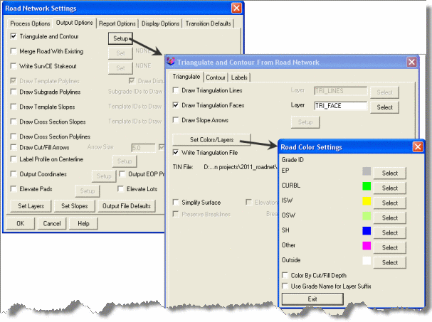
Set Road Colors In the
"Triangulate and Contour From Road Network" Dialog Box
Contour and
Labels tabs...
Use these tabs to define the settings for proposed contours and
contour labels.
Output Options (Continued)
Merge Road with Existing: When enabled, use the
Set button to specify the path and filename of a
third Surface (.TIN) file to be created by merging the Existing and
roadway design Surface (.TIN) files.
Write SurvCE Stakeout: When enabled, use the
Set button to specify the path and filename of a
SurvCE Stakeout (.RNF) file to be exported. This file can be
directly loaded into data collectors using Carlson SurvCE for
unlimited field stakeout of the Road Network.
Draw Template Polylines: When enabled, this option
will draw all 3D polylines used to generate the roadway design
Surface. This option is automatically enabled when the
Triangulate and Contour option is enabled. The
layer for the polylines is set by picking the Set Layers button
in Output
Options.
Draw Disturbed Area: When enabled, this option
will draw a closed, zero-elevation polyline around the limits of
disturbance of the roadway design Surface. The layer for the
polyline is set by picking the Set Layers button
in Output
Options.
Draw Subgrade Polylines: When enabled, this option
will draw all 3D polylines used to generate the roadway subgrade
Surface(s). These polylines can be used to manually generate
additional surfaces for modeling, stakeout or machine control
purposes. Entering an asterisk (*) in the text box will draw
polylines for all Template
IDs. Once a Road has been added to the Network, the
Select button will be activated. Picking the
Select button displays a view of the Template
(.TPL) file at the starting station and allows the user to
Draw polylines for selected Subgrade IDs. If
needed, the Next and Previous
buttons at the bottom of the window allow the user to browse
through the stations of the road design to find a particular
Subgrade ID. The layer for the polylines is set by picking the
Set Layers
button in Output
Options.
 Pick Subgrade Polylines to Be
Drawn
Pick Subgrade Polylines to Be
Drawn
Draw Template Slopes: When enabled, this option
will draw slope arrows parallel to the Centerline at the selected
Template IDs.
This option may be used to indicate direction and steepness of
slope along the flowline of the gutter. Entering an asterisk (*) in
the text box will draw slope arrows for all Template IDs. Once a Road
has been added to the Network, the Select button
will be activated. Picking the Select button
displays a view of the Template (.TPL) file (similar to the one
shown above) and allows the user to Draw polylines
for selected Template
IDs. If needed, the Next and
Previous buttons at the bottom of the window allow
the user to browse through the stations of the road design to find
a particular Template
ID. The layer for the slope arrows is set by picking
the Set
Layers button in Output Options. Other
slope arrow settings are specified by picking the Set Slopes button
in Output
Options.
Draw Cross Section Polylines: When enabled, this
option will draw a 3D polyline defining the roadway design surface
cross-section at each sampled station along the Centerline. These
polylines can be used to manually generate additional surfaces for
modeling, stakeout or machine control purposes. The layer for the
polylines is set by picking the Set Layers button in
Output
Options.
Draw Cut/Fill Arrows: When enabled, this option
will draw arrows at each sampled cross-section station so that the
arrow is pointing down-slope. The example shown below indicates a
section of Cut slope transitioning to a section of Fill slope. Once
enabled, the user has the ability to adjust the size of the arrows
and specify whether or not the Cut/Fill Arrows should be solid.
 Cut/Fill Arrows On Slopes
Label Profile on Centerline: When enabled, this
option labels Profile slopes and critical points such as PVC, PVT,
High and Low Points in plan view along the Centerline. Once
enabled, use the Setup button to open the
Label Profile on Centerline Settings dialog. Then,
from the list of "Available Labels", select the label(s) to be
drawn and use the Add button to shift them to the
list of "Used Labels". Selecting one of the "Used Labels" and then
picking the Setup button allows the user to
configure the label style and settings for each type of label.
 Label Profile on Centerline and Label
Setup Dialog Boxes
Label Profile on Centerline and Label
Setup Dialog Boxes
Output Coordinates: When enabled, this option
allows the user to export a Coordinate (.CRD) file containing all
of the critical points for the Road Network. Once enabled, pick the
Setup button to specify the path, file name and
other criteria for the point file.
 Point Output Settings Dialog
Box
Point Output Settings Dialog
Box
Output EOP Profiles: When enabled, this option
creates individual Profile (.PRO) files for the edges of
pavement.
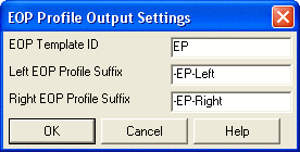 Output EOP Profiles Dialog Box
Elevate Pads: When enabled, this option adjusts
the elevation of closed polylines within a specified proximity of
the Road Network. Once enabled, use the Setup
button to open the Elevate Pad Settings dialog box
and configure the settings.
In the Elevate Pad Settings dialog
box...
Reference Template ID: When determining
the new pad elevation, all distances and elevation changes are
based on the Template
ID specified here. Type the Template ID in the text
box or use the Select button to choose from a
list.
Pad Layer: All original polylines found
on this layer (and within the Max Offset of the Reference Template
ID) will be elevated.
Max Offset: All original polylines within
this distance of the Reference Template ID and on the specified
"Pad Layer" will be elevated.
Reference Elevation: This setting has 3
options: "Highest Elevation", "Lowest Elevation" and "Elevation at
Middle". Of the elevations found along the Reference
Template ID that are adjacent to the pad polyline, the
command will use either the highest, lowest or middle elevation
found to set the new pad elevation.
Slope Type: This setting has 3 options:
Percent (%), Ratio (x:y) and Vertical (change in elevation).
Cut/Fill, Normal/Min/Max Slopes: For
future earthwork balancing adjustments, the settings in this dialog
are used to specify the range of allowable slopes when in cut or
fill conditions.
Assign New Layer: When enabled, this
option allows the user to specify a new layer for the new, elevated
pad polyline. Once enabled, either type the new layer name in the
text box or use the Select button to choose the
layer from a list.
Retain Original Polyline: This option is
only available if the "Assign New Layer" option is enabled and will
keep the original, zero-elevation polyline in addition to the new,
elevated polyline. If this option is not enabled, the original
polyline will be deleted from the drawing.
 Elevate Pad Settings Dialog Box
In the dialog shown here, all closed polylines on layer PAD that
are within 100 feet of the road will have their elevations set
based on a 2 percent grade up from the PAVE Template ID point, in
either Cut or Fill conditions. In future earthwork balancing
adjustments, the polyline can be adjusted a maximum of up to a 10
percent grade or down to a 1 percent grade from the Reference
Template ID. The example below shows the results of elevating a pad
so that it is 2.0' above (using Vertical option) the highest point
along a Reference Template ID of "SH" (Shoulder) on the adjacent
Road.
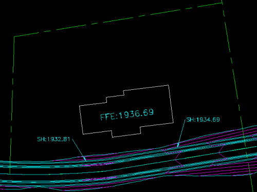 Elevate Pads - Example
Output Options (Continued)
Elevate Lots: When enabled, this option follows a
logic similar to that of the Elevate Pads routine
in that it elevates zero-elevation lot lines relative to a road
design and based on a set of grading rules. Once the option is
enabled, use the Setup button to display the
Elevate Lots Setup dialog box.
In the Elevate Lots Setup dialog
box...
Grading Rules: The necessity of a Grading
Rules (.GRR) file is the key difference between elevating pads and
elevating lots. If a Grading Rules (.GRR) file has already been
prepared, use the Select button to browse to and
select the file. To create a new file, pick the
Edit button to open the Define Grading
Rules dialog box and specify the desired settings. Then,
pick the SaveAs button to Save a
Grading Rules (.GRR) file. Define Grading Rules is
a command that also exists outside of the Road
Network feature. Please refer to the Help
files for that command if additional assistance is needed.
Reference Template ID: When determining
the elevations for the new lot line, all distances and elevation
changes are based on the Template ID specified
here. Type the Template
ID in the text box or use the Select
button to choose from a list.
Input 2D Lot Layer: All original
polylines found on this layer (and within the Max Offset of the
Reference Template ID) will be elevated. Either type the layer name
in the text box or use the Select button to choose
the layer name.
Output 3D Lot Layer: This is the layer to
which the newly elevated lot lines will be assigned. Either type
the layer name in the text box or use the Select
button to choose the layer name.
Front to Ref Max Offset: Use this setting
to specify a distance from the Reference Template
ID beyond which Lot Frontage polylines will not be
elevated.
Back to Ref Max Offset: Use this setting
to specify a distance from the Reference Template
ID beyond which Back/Rear Lot polylines will not be
elevated.
 Elevate Lots and Define Grading Rules
Dialog Boxes
Elevate Lots and Define Grading Rules
Dialog Boxes
Output Options (Continued)
Set
Layers: Pick this button to display the Road
Network Layers dialog box.
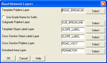 Road Network Layers Dialog Box
Set Slopes: Pick this button to display the
Road Network Slopes dialog box and configure the
settings for drawing slope arrows.
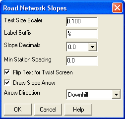 Road Network Slopes Dialog Box
Output File Defaults: Pick this button to specify
additional Centerline (.CL), Profile (.PRO) and Section (.SCT)
files to be saved when Processing the Road Network.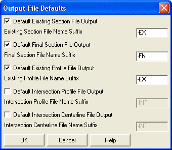
Output File Defaults Dialog
Box
Report Options
Settings on this tab allow the user to specify defaults for the
Road Network Report feature. This feature is
accessible from the Report
button of the Road Network: Task
Pane.
Report Precision: Specify the decimal precision for the
report.
Use Report Formatter: This option allows
for customized report layout and contents. Otherwise a standard
report is displayed.
Report Cut/Fill End Areas:
Specify whether or not to report cut/fill at each
station.
Report Cut/Fill Differences: Adds a
running total of the cut to fill balance at each station to the
report.
Report Cumulative Cut/Fill: Adds a
running total of the cut/fill at each station to the report.
Fill Shrink/Cut Swell Factor: Allows you to specify a value
that the volume calculated will be multiplied by.
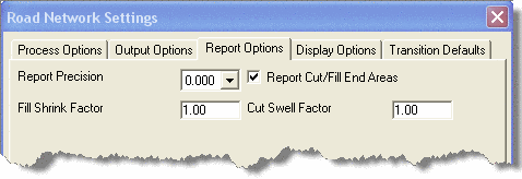 Report Options Tab
Display Options
Settings on this tab allow the user to configure special display
characteristics in order to identify the Road, Intersection or
Cul-de-Sac selected in the Road
Network: Task Pane.
 Display Options Tab
Transition Defaults
Settings in this tab allow the user to specify the default values
used for transitioning from Road to Road, from Road to Intersection
and from Road to Cul-de-Sac.
CL Intersections: Use this setting to define the
default transition distance and vertical curve length for
intersecting Centerlines. See Road Network: Adding and
Editing Intersections for more.
Side Intersections: Use this setting to define the
default vertical curve length for the Profile and the default
radius for Corners at Intersections. See Road Network: Adding and
Editing Intersections for more.
Surface Method: When calculating Intersections,
there are two options for handling the cross-sections of the
intersecting Roads: "Hold Main Crown", which honors the Primary
Road Template through the Intersection, or "Radial from Curb",
which grades between the Centerline Profile and the Profile of each
Corner of the Intersection. The Profile for the Corner may be
defined as the edge of pavement (EP), back of curb (BC) or other
point on the cross-section by specifying the Template ID in the
Settings tab of the Edit Intersection dialog
box.
Surface Method: Radial From Curb Surface
Method: Hold Main Crown
Surface
Method: Hold Main Crown
Transition Method: This setting applies when a
Road has a varying width through an Intersection. The "Across
Intersection" option looks at the Primary Road (from start to end
of the Intersection) to find the maximum offset distance between
the Centerline and edge of pavement, and uses this distance to set
the edge of pavement breakline across the Intersection with the
Secondary Road. The "Mid Point" option simply finds the pavement
width at the Intersection station and uses this distance to set the
edge of pavement breakline across the Intersection.
Cul-de-Sac: Use this setting to define the default
vertical curve length along the Cul-de-Sac Profile.
 Transition Defaults Tab
Road Network: Adding and Editing Roads
Roads in a Road Network are managed in the Road Name area of the Road Network: Task Pane.
Add: Pick this button to Add a Road to the
Network. After adding the Road, the Edit Road dialog box
is displayed allowing the user to manage and make changes to the
Input Files and
Output Files for
the selected Road.
Edit: Pick this button to display the Edit Road dialog box
to manage and make changes to the Input Files and Output Files for the
selected Road.
Remove: Pick this button to delete the selected
Road from the Road Network. After Removing the Road from the
Network the design files associated with that Road will remain in
the project folder.
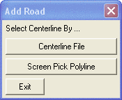
Adding a New Road
Adding a new Road may be done either by selecting a pre-defined
Centerline (.CL) file or by screen-picking a 2D Polyline in the
drawing and assigning a new Centerline (.CL) file to it.
Add: Use this button to Add a
Road to the Road Network or right-click on Roads in the project
tree and pick Add Road. After picking the Add
button, the Add Road dialog box gives the user the
option to "Select Centerline By..." Centerline
File or Screen Pick Polyline. If the
Centerline File option is chosen, the user is
prompted to browse to and select the Centerline (.CL) file.
 Specify Method to Use to Add
Road
Specify Method to Use to Add
Road
If the Screen Pick Polyline option is chosen, the
user is prompted to select a polyline in the drawing. If an
associated Centerline (.CL) file is not found in the project
folder, the Set Centerline dialog notifies the
user that, "No centerline file associated with polyline..." and the
user must choose to either select another polyline or to
Assign Centerline File to Polyline.
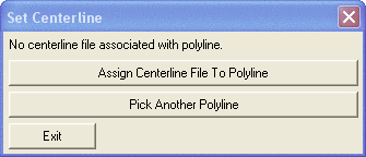 Set Centerline Dialog Box
After picking the Assign Centerline File to
Polyline button, the Centerline to Set
file dialog box prompts the user to assign a path and filename for
the new Centerline (.CL) file.
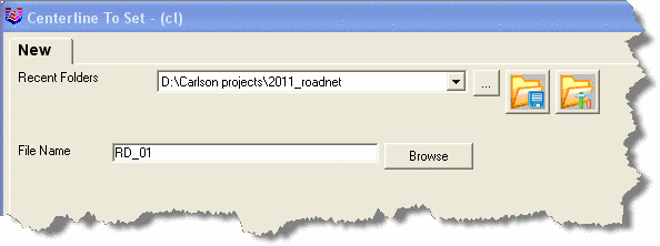 Centerline to Set File Dialog
Box
Centerline to Set File Dialog
Box
Immediately upon defining the new Road, the Profile to
Use file dialog box prompts the user to assign a path and
filename for the proposed Profile (.PRO) file for the Road. By
default, the new Profile (.PRO) file is named the same as the
Centerline (.CL) file.
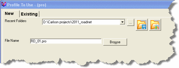
Profile to Use File Dialog
Box
Edit Road Dialog Box
After specifying the Centerline (.CL) and Profile (.PRO) files for
the Road, the Edit Road dialog box is displayed.
This dialog serves as the "manager" for all files relating to the
specific Road. The Edit Road dialog box allows the
user to apply settings and associate various files that are
specific to the Road - not the entire Road Network. The
Edit button in the Road Name
section of the Road Network: Task Pane also
displays this dialog box.
Edit Road Dialog
Box
Intersection Only: If this option is enabled, Road
Network will only consider the portions of this Road that intersect
with other Roads when calculating the design.
Full Range: This option will process the full station range
of the road. Otherwise, turn this option off and set the Station
Range to process a subset of the road.
Station Settings: Pick this
button to display for special stations and cut/fill gaps.
Special Stations: Enter
one or more stations at which to sample cross-sections.
Cut/Fill Gaps: Use the Add
and Remove buttons to define a series of station ranges for
cut/fill gaps where the program will not calculate any volumes or
apply the template cut/fill tie slopes. For example, these stations
could be used across a bridge.
 Add Road Specific Special Stations
Road Input Files
A Centerline (.CL) file, a Profile (.PRO) file and a Template
(.TPL) File are required in order
to process a roadway design using the Road Network
feature. In addition, the Road Network feature
accepts several additional files for designing Roads using specific
criteria. In the Edit Road dialog box, picking the
buttons on the left, that are labeled with the file type, will
display a file dialog box prompting the user to select an existing
or create a new file of that type. The corresponding
Edit button to the right of each file type will
display the editor for that file type.
Required Road Input Files
Centerline: Pick this button to select an existing
or create a new Centerline (.CL) file from which to define the
horizontal alignment of the Road. The Edit button
opens the Centerline File Editor. This Editor is
the same as the one used for the Input-Edit Centerline
File command. Please refer to the Help
files for that command if additional assistance is needed.
 Centerline File Editor
Profile: Pick this button to select an existing or
create a new design Profile (.PRO) file for the Road. The
Edit button opens the Input-Edit Road
Profile Editor. The Editor provides the user with both a
"profile-grid-view" and a "table-view" of the Profile (.PRO) file.
See Road Network: Road
Profile Editor for more.
 Input-Edit Road Profile Editor
Template: Pick this button
to select an existing or create a new Template (.TPL) file or
Template Series (.TSF) file for the Road.
A Template (.TPL) file defines a typical roadway cross-section
including pavement, curb, ditches, medians, super-elevations,
subgrades, rights-of-way and cut/fill slopes. One of the most
critical steps in defining a Road Template for use with the
Road Network feature is the assigning of a
Template ID to points on the Template. A
Template ID is a unique name for each point on the
Template and is used to transition from Road to Road, from Road to
Intersection and Road to Cul-de-Sac. The Template
ID serves 4 purposes: (1) the ID will be applied as a
description to all final Template points generated in the form of a
Coordinate (.CRD) file, (2) the ID can be used as a design point in
the Template definition, as in EP+5 indicating 5 feet or meters
right of edge of pavement, (3) points of common ID may be connected
by 3D polylines in the Output Options tab of
the Road Network:
Settings dialog box and (4) Quantities can be
generated with reference to the ID and material (gravel, concrete,
etc.) also defined in the Template (.TPL) file.
A Template Series (.TSF) file references Template (.TPL) files for
Template-to-Template transitioning and is one method used for
widening and narrowing of Road sections.
Picking the Edit button will open the appropriate
Design Template or Input-Edit Template
Series File Editor. These Editors are the same as those
used for the Draw Typical Template and
Template Transition commands. Please refer to the
Help files for those commands if additional
assistance is needed.
 Design Template Editor
 Input-Edit Template Series Editor
Optional Road Input Files
Super Elevation: Pick this button to select an
existing or create a new SuperElevation (.SUP) file for the Road.
The Edit button opens the Super
Elevation Editor. This Editor is the same as the one used
for the Input-Edit Super Elevation command. Please
refer to the Help files for that command if
additional assistance is needed.
 Input-Edit Super
Elevation
Input-Edit Super
Elevation
Topsoil Removal: Pick this button to select an
existing or create a new Topsoil Removal (.TOP) file for the Road.
This file allows the user to define topsoil removal and replacement
zones to be used in the Road design. Different topsoil depths can
be used for different station ranges and then are computed as part
of the cut and fill volumes. The Edit button opens
the Topsoil File Editor. This Editor is the same
as the one used for the Topsoil
Removal/Replacement command. Please refer to the
Help files for that command if additional
assistance is needed.
 Topsoil Removal/Replacement
Editor
Topsoil Removal/Replacement
Editor
Template Transition: Pick this button to select an
existing or create a new Template Transition (.TPT) file for the
Road. This file allows the user to define changes in grade
distances or slopes for a specific Template ID through a range of
stations and is another method of widening and narrowing Road
sections. The Edit button opens the
Template Transition Editor. This Editor is the
same as the one used for the Template Transition
command. Please refer to the Help files for that
command if additional assistance is needed.
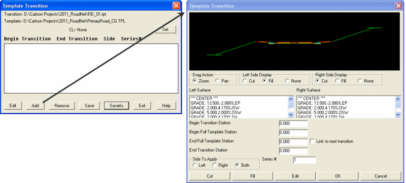 Template Transition Editor
Template Grade Table: Pick this button to select
an existing or create a new Template Grade Table (.TGT) file for
the Road. This file allows the user to define specific slopes and
distances for one or more Template IDs (and for left and right
sides independently) that have been assigned in the Template (.TPL)
file. The Edit button opens the Template
Grade Table Editor. This Editor is the same as the one
used for the Template Grade Table command. Please
refer to the Help files for that command if
additional assistance is needed.
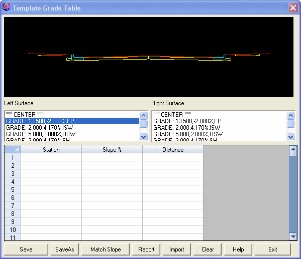 Template Grade Table
Template Pt Profile: Pick this button to select an
existing or create a new Template Point Profile (.TPP) file for the
Road. This file allows the user to assign separate Profile (.PRO)
files to specific Template IDs that have been defined in the
Template (.TPL) file. This accommodates varying grade changes (for
a ditch, for instance) independent of the Profile for the
Centerline. The Edit button opens Define
Template Alignments and then picking the
Add button displays the Template Point
Profile Settings dialog box. These dialog boxes are the
same as the ones used for the Assign Template Pt
Profile command. Please refer to the Help
files for that command if additional assistance is needed.
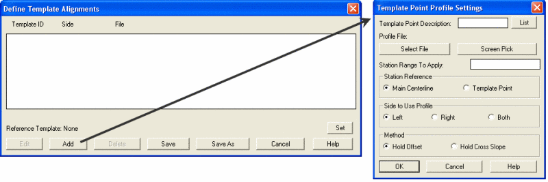 Assign Template Pt Profile Dialog
Boxes
Assign Template Pt Profile Dialog
Boxes
Template Pt Centerline: Pick this button to select
an existing or create a new Template Point Centerline (.TPC) file
for the Road. This file allows the user to assign separate
Centerline (.CL) files to specific Template IDs that have been
defined in the Template (.TPL) file. This accommodates varying
widths for cross-section surfaces and provides an additional method
of managing widening and narrowing of Roads. The
Edit button opens Define Template
Alignments and then picking the Add
button displays the Template Point Centerline
Settings dialog box. These boxes are the same as the ones
used for the Assign Template Pt Centerline
command. Please refer to the Help files for that
command if additional assistance is needed.
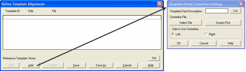 Assign Template Pt Centerline Dialog
Boxes
Assign Template Pt Centerline Dialog
Boxes
ROW Offsets: The ROW feature draws 2D linework at
specified offsets from the centerline. In the dialog, there are
settings for the layer for the 2D polyline and the offsets left and
right of the centerline. There is also a list of additional offsets
to draw. Use the Add, Edit and Remove buttons to setup this list of
offsets to draw. The names, offsets and layers for these 2D
polylines is stored to a .ROW file.
Road Design Parameters: Pick this button to select an
existing or create a new Road Design Parameters (.RDP) file for the
Road. This file allows the user to define a set of Road design
standards to compare against a roadway design. The Road Network
Process function will report a warning when the design is out of
compliance with these parameters. The Road Design Parameters can be
specific to all stations along a Road or, in the event speed limit
or other changes must be applied, a range of stations. The
Edit button opens the Road Design
Parameters dialog box. This box is the same as the one
used for the Define Road Design Parameters
command. Please refer to the Help files for that
command if additional assistance is needed.
 Road Design Parameters Dialog
Box
Road Design Parameters Dialog
Box
Road Stripes: This option draws plan view
polylines for road stripes such as double yellow lines along the
centerline and dashed white lane lines. See the Draw Road Stripes
command for a description of this feature.
Cut Benches: Pick this button to specify up to 4
triangulation surface files to use when the "Slopes In Series" and
"Cut to Surface" options are used in the Template (.TPL) file. In
cut conditions, the program will look to intersect with these
surfaces before it reaches the final target surface which is the
Existing Surface set under Settings.
Optional Road Output Files
Existing Section File: Pick this button to specify
the path and filename for the existing cross-section file to be
written. The default filename is set by picking Output File Defaults
button in the Output
Options tab of the Road Network Settings
dialog box.
Final Section File: Pick this button to specify
the path and filename for the final/design cross-section file to be
written. The default filename is set by picking Output File Defaults
button in the Output
Options tab of the Road Network Settings
dialog box.
SuperElevation Diagram: Pick this button to
specify the path and filename for the SuperElevation Diagram (.SUD)
file to be written.
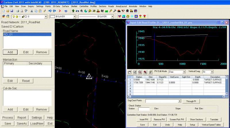
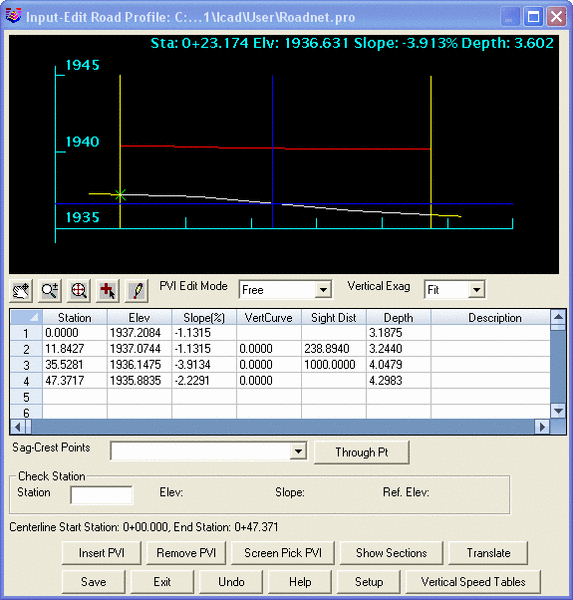
Road Profile Editor
The Input-Edit Road Profile Editor is accessible
from the Edit
Road Dialog box.
 Pick "Edit" to Access the Input-Edit Road
Profile Editor
Pick "Edit" to Access the Input-Edit Road
Profile Editor
In Carlson's Road Network feature, the initial
design Profile is automatically generated and has only a starting
and ending PVI - with the elevation at both ends tying into
existing ground. The crosshairs are locked to the design
Profile.
The initial PVIs can be seen in the profile-grid-view where the
existing ground Profile is shown in red and the design Profile in
white. The initial PVIs are shown in the table-view with the "PVI
Description" indicating the PVI elevation is tied to the
"TARGET-SURFACE" (existing ground).
The buttons and settings directly below the profile-grid-view allow
the user to edit the Profile and adjust the Zoom and Scale factors
of the profile-grid-view. The Insert PVI,
Remove PVI and Screen Pick PVI
buttons at the bottom of the dialog box allow the user to make
changes to the Profile using the table-view.
 Input-Edit Road Profile
Editor
Input-Edit Road Profile
Editor
The profile-grid-view provides the user with a dynamic viewer and
editor. As the crosshairs move along the design Profile, a
"station" symbol on the drawing screen indicates the corresponding
position/station along the Centerline. Also, as the crosshairs move
along the Profile, the current Station, Elevation, Slope and Depth
(between design and existing ground Profiles) are displayed and
dynamically updated at the top of the window. The starting and
ending stations for the Centerline are displayed above the buttons
at the bottom of the window.
 Input-Edit Road Profile Editor with Station
Indicator in Drawing
Input-Edit Road Profile Editor with Station
Indicator in Drawing
 Pan, Zoom and
Zoom Extents: Use these buttons to change the Zoom
factor in the profile-grid-view.
Pan, Zoom and
Zoom Extents: Use these buttons to change the Zoom
factor in the profile-grid-view.
 Add PVI: Use this button to "screen
pick" the location for a new PVI in the profile-grid-view. After
screen picking the new PVI location, the New PVI
box prompts the user to provide additional design criteria to set
the new PVI.
Add PVI: Use this button to "screen
pick" the location for a new PVI in the profile-grid-view. After
screen picking the new PVI location, the New PVI
box prompts the user to provide additional design criteria to set
the new PVI.
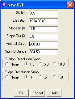 New PVI Dialog Box
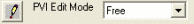 Edit PVI and PVI Edit
Mode: Use the Edit PVI button to change
the elevation and station of a PVI in the profile-grid-view by
dragging-and-dropping it to a new location. The default PVI
Edit Mode is "Free" which allows 360-degree motion when
dragging-and-dropping the PVI. Other PVI Edit Mode
options are: Hold Slope In,
Hold Slope Out, Hold Station
and Hold Elevation. The user also can choose to
Hold Vertical Curve Length,
Hold K-Value or Hold Sight
Distance when editing the PVI using drag-and-drop.
This setting is controlled in the Road Profile Settings
dialog box.
Edit PVI and PVI Edit
Mode: Use the Edit PVI button to change
the elevation and station of a PVI in the profile-grid-view by
dragging-and-dropping it to a new location. The default PVI
Edit Mode is "Free" which allows 360-degree motion when
dragging-and-dropping the PVI. Other PVI Edit Mode
options are: Hold Slope In,
Hold Slope Out, Hold Station
and Hold Elevation. The user also can choose to
Hold Vertical Curve Length,
Hold K-Value or Hold Sight
Distance when editing the PVI using drag-and-drop.
This setting is controlled in the Road Profile Settings
dialog box.
Vertical Exag: Use
this setting to "Fit" the Profile into the profile-grid-view area
of the window or use other pre-defined options such as "x1", "x2",
"x5" and "x10" to exaggerate the vertical scale by 1-, 2-, 5- or
10-times.
Sag-Crest Points: After adding one or more
vertical curves to the design Profile, a list of the "sag" and
"crest" points along the Profile will be listed in the drop-down
box.
Through Point: After selecting a PVI in the
table-view, pick this button to force a sag or crest point to a
specific station and elevation.
Check Station: To find the precise Elevation,
Slope and Reference Elevation (existing ground) for a specific
station, enter the station in the text box and press
Enter.
Insert PVI: Before picking the Insert
PVI button, the user must use the mouse to
select/highlight a cell in the profile table-view. Then, picking
the Insert PVI button will create a blank row,
above the selected row, allowing
the user to enter the information for the new PVI.
Remove PVI: Before picking the Remove
PVI button, the user must use the mouse to
select/highlight a cell in the row corresponding to the PVI to be
removed. Then, picking the Remove PVI button will
delete the selected row/PVI from the Profile.
Screen Pick PVI: Picking this button allows the
user to change the station of a PVI by screen picking a location in
the drawing. Before picking the Screen Pick PVI
button, the user must use the mouse to select/highlight a cell in
the corresponding row of the PVI to be changed. Then, picking the
Screen Pick PVI button changes the user to the
active drawing screen, prompting the user to "Pick PVI Point:" in
the drawing area.
Show Sections: This option is only available if
the Template (.TPL) file for the Road has already been specified in
the Edit Roads dialog box. When picked, the
Show Sections button will open a "Road Design
Section Data" viewer window while keeping the "Road Profile" window
open as well. This provides the user a dynamic design environment
in which the plan-, profile- and section-views are visible at one
time. Additionally, when the "Section" viewer window is open, the
notes at the top of the profile-grid-view include the "Cut" and
"Fill" end-area at the current station along with the "Cut" and
"Fill" volume for the entire Road. These calculations are dynamic
and will update if changes are made to the design Profile. Use the
Specific Station to check the section at a station. Or move the
cursor in the profile preview graphic to change the section
station.
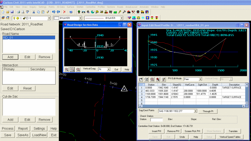 Road Profile View and Section Viewer with
Station Indicator in Drawing
Road Profile View and Section Viewer with
Station Indicator in Drawing
Translate: Picking this button will display the
Translate Profile dialog box and allows the user
to change the elevation of the entire Profile or a range of
stations along the Profile.
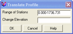 Translate Profile dialog box
Save: This button saves changes to the Profile
(.PRO) file.
Exit: This button exits the Input-Edit
Road Profile editor dialog box.
Undo: This button will undo the last change made
to the Profile.
Setup: This button opens the Road Profile Settings
dialog box. See below for more information.
Vertical Speed Tables: Use this button to specify
the Vertical Curve Speed Table (.VST) files to use for the design
of this Road.
Road Profile Settings
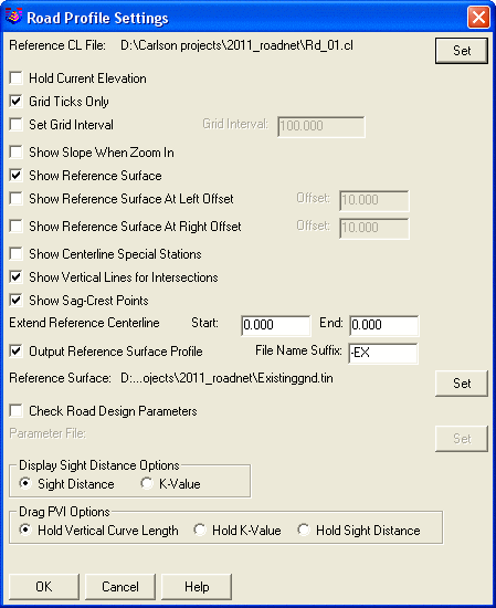 Road Profile Settings Dialog
Box
Road Profile Settings Dialog
Box
Reference CL File: In the Road
Network feature, the "Reference CL File" is automatically
set to the Centerline (.CL) file associated with the Road.
Hold Current Elevation: When enabled and
the station and elevation of a PVI changes, the "Slope Out" of the
adjusted PVI will change but the elevation of the next PVI will be
left unchanged. Otherwise, if not enabled, the "Slope Out" of the
adjusted PVI is held and the elevation of the next PVI is
changed.
Grid Ticks Only: When enabled, only grid
ticks will be shown in the profile-grid-view. Otherwise grid lines
will be used.
Set Grid Interval: If enabled, this
option allows the user to manually specify the grid- or grid-tick
interval shown in the profile-grid-view.
Show Slope When Zoom In: When enabled,
this option allows the user to display the slopes on those vertical
tangents that are long enough to display a slope label when
Zoom-ing in closer to the Profile.
Show Reference Surface: When enabled,
this option displays the Profile of a "Reference Surface" in
addition to the design Profile. The "Reference Surface" is
typically the original or existing ground Profile.
Show Reference Surface at Left Offset:
When enabled, this option allows the user to see an additional
Profile that is offset horizontally from the "Reference
Centerline". The offset distance can be specified after the option
is enabled.
Show Reference Surface at Right Offset:
When enabled, this option allows the user to see an additional
Profile that is offset horizontally from the "Reference
Centerline". The offset distance can be specified after the option
is enabled.
Show Centerline Special Stations: When
enabled, critical Centerline stations such as PC, PT, SC, ST, TS
and SP are shown in the profile-grid-view.
Show Vertical Lines for Intersections:
When enabled, this option will display a vertical line representing
the Centerline and Edge of Pavement stations for other Roads in the
Road Network.
Show Sag-Crest Points: When enabled, this
option displays a marker at the sag and crest points of each
vertical curve.
Extend Reference Centerline: When
enabled, the user may provide an extended range of stations so as
to show Profile data beyond that generated along the associated
Centerline (.CL) file. For instance, for a new Road tying into an
existing Road (proposed CL file starts at the Intersection of the
Centerline of the existing Road) an extended range of stations may
be desired in order to see the Profile of the cross-slope, curb,
ditch and slope across both sides the existing Road.
Output Reference Surface Profile and
Suffix: When enabled, this option will generate an
existing ground Profile (.PRO) file and allows the user to specify
a suffix for the filename. The defaults for this option are set
using the Output File
Defaults button in the Output Options
tab of the Road Network
Settings dialog box.
Reference Surface: The "Reference
Surface" is an additional surface Profile shown in the
profile-grid-view alongside the design Profile. For the
Road Network feature, the "Reference Surface" is
the surface specified as "Existing Ground" in Road Network Settings
dialog box.
Check Road Design Parameters: When
enabled, this option will compare the current Road design to an
established set of design parameters set in a Road Design
Parameters (.RDP) file. Please refer to the Help
files for the Road Design Parameters command if
additional assistance is needed.
Display Sight Distance Options: Use this
radio button to display either a "Sight Distance" or "K-Value"
column in the profile-table-view.
Drag PVI Options: Use this radio button
to specify the design criteria to "hold" when using the
Edit/Drag PVI command in the profile-grid-view.
The options are to "Hold Vertical Curve Length", "Hold K-Value" or
"Hold Sight Distance".
Road Network: Adding and Editing Intersections
Intersections are created automatically in the Road
Network feature without any input from the user. Once
Intersections are identified, they are listed and managed in the
Intersection area of the Road Network: Task Pane.
Edit: Use this button or right-click on the
intersection in the project tree and choose Edit Intersection to
display the Edit
Intersection dialog box and make changes to the
Input Data
and Output
Files for the selected Intersection. Other changes
that can be made to the Intersection design are:
1) Changing the Primary/Secondary status of the Roads creating the
Intersection,
2) Making design changes that apply to the entire Intersection,
3) Making design changes that apply to one or more Corners of the
Intersection.
Reset: Use this button to overwrite all design
changes made to the selected Intersection and reset to the original
Intersection design.
As stated above, Intersections are created automatically in the
Road Network feature without any input from the
user. Road Network recognizes and calculates the Intersection using
the Centerline (.CL) files associated with the Roads in the
Network. If two Roads are added to the Network and they share one
or more common point, an Intersection is created and displayed as
an Intersection in the Road Network:
Task Pane.
For all Intersections, one of the two Roads creating the
Intersection will be the "Primary" Road and the other will be the
"Secondary" Road. When setting grade through an Intersection, the
Primary Road's Template (.TPL) file takes priority and is used to
define the cross-section. The grades of the Secondary Road will
adjust to match the Primary Road. Additionally, changes to any of
the Primary Road design files - such as the Profile (.PRO) file -
will automatically update the affected file(s) of the Secondary
Road.
Upon creation of an Intersection, the Road Network
feature automatically designates one of the Roads as the Primary
Road and the other as Secondary. For four-way Intersections, the
first Road added to the Road Network will be deemed the Primary
Road and the second Road will be Secondary. For T-Intersections,
the Road going straight-through the Intersection will be deemed the
Primary Road - even if it's added to the Network after the Road
that stops at the Intersection. The user can change the Primary
Road designation in the Edit Intersection dialog
box.
Edit Intersection
Picking the Edit button displays the Edit
Intersection dialog box which has a
Settings tab and, depending on the type of
Intersection, 2 or 4 additional tabs - each representing one
Corner of the Intersection. The Corner tabs are labeled
Front-Right,
Back-Right,
Front-Left or Back
Left. T-Intersections will have 2 tabs and 4-way
Intersections will have 4 tabs.
Intersection Settings
At the top of the Settings tab, the station and
elevation of the Intersection is shown for all Roads.
 The
Settings Tab of the Edit Intersection Dialog Box
The
Settings Tab of the Edit Intersection Dialog Box
Primary Road: Use the radio button to specify the
Primary Road of the Intersection.
Profile
Transition PVI Distance: This value represents the
distance beyond the edge of pavement of the Primary Road (along the
Secondary Road Centerline) that the cross-slope of the Primary Road
will be extended.
Profile Transition VC Length: This setting allows
the user to specify the length of vertical curve to be inserted at
the PVI where the extension of the Primary Road's cross-slope and
the Centerline of the Secondary Road meet.
 "Profile Transition PVI Distance" and
"Profile Transition VC Length"
"Profile Transition PVI Distance" and
"Profile Transition VC Length"
Template ID: This is
the point on the cross-section used to define the horizontal
(Centerline) and vertical (Profile) alignments around the Corners
of the Intersection. Also, the profile for the side road will tie
into this Template ID on the main road. The Template ID may be
specified as any point on the cross-section - such as edge of
pavement (EP) or the back of curb (BC) - as long as it has been
defined as a Template
ID in all of the Template (.TPL) files used to
calculate the Intersection. Type the Template ID in the text
box or use the Select button to choose from a
list.
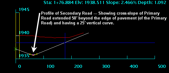
Hinge Profile and 2nd ID:
For the side road profile, this is an optional second point to
match from the main road template.
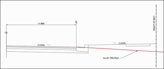 Cross-section of main road showing side
(alley) profile tying into single Template ID at flow
line
Cross-section of main road showing side
(alley) profile tying into single Template ID at flow
line
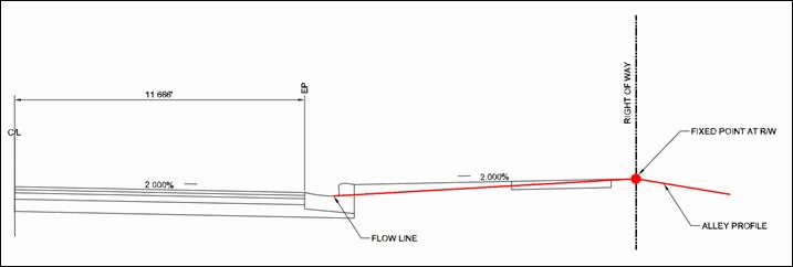 Cross-section of main
road showing side (alley) profile tying into Template ID at flow
line as well as 2nd Hinge at Right-of-way of main road
Cross-section of main
road showing side (alley) profile tying into Template ID at flow
line as well as 2nd Hinge at Right-of-way of main road
Surface Method: See the Transition Defaults
section above for details on this setting.
Transition Method: See the Transition Defaults
section above for details on this setting.
Link Secondary Centerline for T-Intersection: When
this option is enabled, changes to the Centerline (.CL) file of the
Primary Road will, if necessary, force the Centerline of the
Secondary Road to be extended or trimmed in order to keep the
Intersection intact.
Note: The default value for several design criteria such as
Intersection radius and length of vertical curve can be set in the
Transition
Defaults tab of the Road Network: Settings
dialog box.
Corner tabs - Front-Right, Back-Right,
Front-Left, Back-Left
Depending on the type of Intersection ("T" or 4-way), there will be
either 2 or 4 additional tabs available in this dialog box. Each of
these tabs represent a Corner of the Intersection and allows the
user to specify horizontal and vertical Input Data and
Output
Files specifically for that Corner.
 One of the "Corner" Tabs of the Edit
Intersection Dialog Box
One of the "Corner" Tabs of the Edit
Intersection Dialog Box
Intersection Input
Data
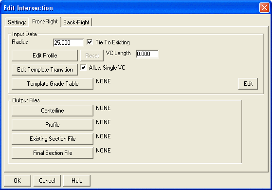
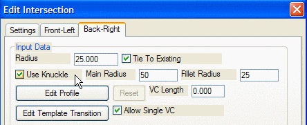
Radius: Use this value to specify the radius of
the curve for this Corner of the Intersection. The Intersection Template
ID specified in the Intersection Settings
tab of this dialog box determines the point on the cross-section
being affected by this setting.
Tie to Existing: Enable this option to keep cut
and fill slopes from projecting to the existing ground through the
Intersection. In areas of steep cut or fill, this setting helps
avoid overlapping Road and Intersection tie slopes.
Edit Profile: Pick this button to open the
Input-Edit Road Profile Editor and make changes to
the Profile for this Corner of the Intersection. The Intersection Template
ID specified in the Intersection Settings
tab of this dialog box determines the point on the cross-section
being represented in the Profile Editor. See Road Network: Road Profile
Editor for more Help with this
feature.
 Edit Profile for a Corner of an
Intersection
Edit Profile for a Corner of an
Intersection
Reset: Use this button to overwrite all edits to
the Profile of the Corner of the Intersection and reset to the
original Profile.
Edit Template Transition: Pick this button to
display the Edit Intersection Transition dialog
box. This allows the user to control the stations for transitioning
through the Intersection from a Template on one Road to a different
Template on another Road. These Transition stations only apply when
the Roads in an Intersection have been assigned different Template
(.TPL) files.
 Edit Intersection Transition Dialog
Box
Edit Intersection Transition Dialog
Box
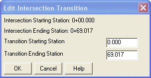
In the Intersection Transition Dialog
Box... The Starting and Ending Stations of the
Intersection transition are displayed at the top of the dialog
box.
Transition Starting Station: This is the
station at which the Primary Road Template ends.
Transition Ending Station: This is the
station at which the Secondary Road starts.
Allow Single VC: When the difference in grade at
the Intersection between the Primary Road and the Secondary Road is
too severe, two intermediate PVIs must be inserted into the Profile
of the Corner of the Intersection in order to properly transition
from one Road to another. In some cases, the transition is possible
using only one intermediate PVI in the Corner Profile. If this
option is enabled and if the intersecting grades allow it, only one
intermediate PVI will be inserted. If this option is not enabled,
two intermediate PVIs will be inserted regardless of the
intersecting grades.
Template Grade Table: Pick this button to select
an existing or create a new Template Grade Table (.TGT) file
defining the grades for the Corner of the Intersection. This file
allows the user to define specific slopes and distances for one or
more Template IDs
that have been assigned in the Template (.TPL) file. The
Edit button opens the Template Grade
Table Editor. This Editor is the same as the one used for
the Template Grade Table command. Please refer to
the Help files for that command if additional
assistance is needed.
"L" Intersection with
Knuckle: When two centerlines connect at a right angle for
an "L" intersection, there is a Use Knuckle option for the outside
corner that can be used to make a knuckle bulb.
 Intersection Output
Files
Intersection Output
Files
Centerline: Pick this button to output a
Centerline (.CL) file representing the horizontal alignment around
this Corner of the Intersection. The Intersection Template
ID specified in the Intersection Settings
tab determines the point on the cross-section exported to the
Centerline (.CL) file.
Profile: Pick this button to output a Profile
(.PRO) file representing the vertical alignment around this Corner
of the Intersection. The Intersection Template
ID specified in the Intersection Settings
tab determines the point on the cross-section exported to the
Profile (.PRO) file.
Existing Section File: Pick this button to output
an Existing Section (.SCT) file for this Corner of the
Intersection.
Final Section File: Pick this button to output a
Final Section (.SCT) file for this Corner of the Intersection.
Additional Transitions tab
Additional Profile Transition
Distance: This option adjusts the transition PVI station on
the side profile. The transition station starts as the offset of
the Template ID on the main road. The cross slope of the main road
is used up to the transition station. For example, if the Template
ID is for edge of pavement up to the gutter pan at 11.67 and the
side profile needs to match the main crown up the flow line at
13.00, then the Additional Transition Distance should be set to
1.33. Additional CL Distance (Front
Main, Back Main, Left Side, Right Side): These options allow
you to extend the station range of the intersection. By default the
intersection station range is between the PC points where the
intersection arcs begin.
Additional CL Distance (Front
Main, Back Main, Left Side, Right Side): These options allow
you to extend the station range of the intersection. By default the
intersection station range is between the PC points where the
intersection arcs begin.
Road Network: Adding and Editing Cul-de-Sacs
Cul-de-Sacs may be added to any Road in the Network and are managed
in the Cul-de-Sac area of the Road Network: Task Pane.
Add: Pick the Add button or right-click on
Cul-de-sacs in the project tree and choose Add to display a list of
Roads in the Network and prompt the user to "Select Road
for Cul-de-Sac".... After selecting the Road, the
Edit Cul-de-Sac dialog box is displayed allowing
the user to specify the Input
Data and Output
Files for the Cul-de-Sac.
Edit: Use this button to display the Edit
Cul-de-Sac dialog box and make changes to the Input Data and Output Files for the
selected Cul-de-Sac.
Remove: Use this button to Remove
the selected Cul-de-Sac from the Road.
Add Cul-de-Sac
Add: Picking this button displays a dialog box
listing the Roads in the Network and prompting the user to
Select Road for Cul-de-Sac.
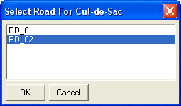 Select Road for Cul-de-Sac
After choosing the Road and picking the OK button,
the Edit Cul-de-Sac dialog box is displayed.
Edit Cul-de-Sac
 Edit Cul-de-Sac Dialog
Box
Edit Cul-de-Sac Dialog
Box
Cul de Sac
Input Data
Cul-de-Sac Centerline Position: Use this radio
button to specify whether the Cul-de-Sac is drawn at the starting
or the ending station of the Centerline.
Centerline Direction: This setting applies only if
the horizontal alignment of the Cul-de-Sac is to be saved
externally as an Output
Centerline (.CL) file. If so, this setting determines
which end of the Cul-de-Sac is the starting and which is the ending
station of the new Centerline (.CL) file.
Center Station: Use this setting to precisely
locate the center of the Cul-de-Sac along the Road Centerline. By
default, the Center Station is the starting or
ending station of the Centerline depending on whether the user has
chosen Start or End as the
desired Cul-de-Sac Centerline Position. The
station for the center of the Cul-de-Sac may also be entered in the
text box or may be specified using a Delta value.
When using the Delta option, the Cul-de-Sac will
be shifted the specified distance along the Centerline.
Cul-de-Sac Radius: Use this value to specify the
radius of the Cul-de-Sac bulb. The Cul-de-Sac Template ID
determines the point on the cross-section being affected by this
setting.
Fillet Radius: Use this value to specify the
radius of the curve that transitions between the Road and the
Cul-de-Sac. The Cul-de-Sac
Template ID determines the point on the cross-section
being affected by this setting.
Offset: When set to "0", this setting places the
center of the Cul-de-Sac on the Centerline of the Road. Setting
this value to a negative(-), greater than "0" value will shift the
center of the Cul-de-Sac left of the Centerline by that distance. A
positive, greater than "0" value will shift it to the right by that
distance.
Tear Drop Mode: Enabling this option creates a
longer transition between the Road and the Cul-de-Sac. When
enabled, a value larger than the Cul-de-Sac Radius
must be entered as the Setback. An example of a
"Tear Drop" Cul-de-Sac having a 45' radius and 75' setback is shown
below.
 Example of Tear Drop
Cul-de-Sac
Example of Tear Drop
Cul-de-Sac
Template
ID: This is the point on the cross-section used to define
the horizontal (Centerline) and vertical (Profile) alignments
around the bulb of the Cul-de-Sac. The Template ID may be specified
as any point on the cross-section - such as edge of pavement (EP)
or the back of curb (BC) - as long as it has been defined as a
Template ID in
the Template (.TPL) file used for the Road. Type the Template ID in the text
box or use the Select button to choose from a
list.
Profile Transition VC: When adding a Cul-de-Sac to
the Road Network, the Profile around the Cul-de-Sac is
automatically generated having 3 PVIs - one on each end connecting
to the Road and one at the mid-point of the alignment. The
Profile Transition VC setting is the default
length of vertical curve inserted at the middle PVI of the Profile.
As shown below, adding a vertical curve at this PVI can have a
significant, positive impact on the resulting surface model and
contours of the Road Network.
 Effect of Adding a Vertical Curve to
Cul-de-Sac Profile
Effect of Adding a Vertical Curve to
Cul-de-Sac Profile
Edit Profile: Pick this button to open the
Input-Edit Road Profile Editor and make changes to
the Profile of the Cul-de-Sac. The Cul-de-Sac Template ID
determines the point on the cross-section being represented in the
Profile Editor. See Road
Network: Road Profile Editor for more
Help with this feature.
 Edit Profile for a Cul-de-Sac
Reset: Use this button to overwrite all edits to
the Profile of the Cul-de-Sac and reset to the original
Profile.
Template: Use this button to browse to and select
an existing Cul-de-Sac Template (.TPL or .TSF) file. Specifying a
different Template than the main Road allows the user to define
different features for the Cul-de-Sac area such as sidewalk and
curb.
Cul de Sac
Output Files
Centerline: Pick this button to
output a Centerline (.CL) file representing the horizontal
alignment around the Cul-de-Sac. The Cul-de-Sac Template ID
determines the point on the cross-section exported to the
Centerline (.CL) file.
Profile: Pick this button to output a Profile
(.PRO) file representing the vertical alignment around the
Cul-de-Sac. The Cul-de-Sac
Template ID determines the point on the cross-section
exported to the Profile (.PRO) file.
Existing Section File: : Pick this button to
output an Existing Section (.SCT) file for the Cul-de-Sac.
Final Section File: Pick this button to output a
Final Section (.SCT) file for the Cul-de-Sac.
Note: Driveways around a cul-de-sac can be easily added simply by
drawing polylines for their centerlines and snapping them to the
EOP of the cul-de-sac.
Workflow Example 1
Step 1: Start Road Network and Configure Settings
Open a Drawing (.DWG) file containing the 2D zero-elevation
polylines representing Road Centerlines for the project. Start the
Road Network command and create a
New Road Network (.RDN) file. After creating the
Road Network file, the Road Network
Task Pane loads as a docked dialog-box on the left
side of the drawing screen.
Configure the Road Network by picking the
Settings button and displaying the Road Network Settings
dialog box. In the Process Options tab,
pick the Existing Surface button and
browse to and select the Existing Ground Surface (.TIN or .FLT)
file to be used for the project.
 Process Options Tab
Next, switch to the Output Options
tab and pick the Setup button next
to Triangulate and Contour. Select the
Write Triangulation File option and then
pick the Browse button to set the path
and filename for the design Surface (.TIN) file for the Roads.
Output Options
Tab
Also in the Output Options tab, pick the
Output File Defaults button to display the
Output File
Defaults dialog box. Pick the Output
File Defaults button to specify additional Centerline
(.CL), Profile (.PRO) and Section (.SCT) files to be saved when
Processing the Road Network.
Output File Defaults Dialog
Box
Next, review the Report
Options, Display Options and
Transition
Defaults tabs of the Road Network
Settings dialog box and make any necessary changes.
Report Options
Tab
Display Options Tab
Transition Defaults Tab
Pick the OK button to close the
Road Network Settings dialog box and then pick
the Save button on the Task
Pane to save the settings to the Road Network (.RDN)
file.
Step 2: Add Roads to the Network
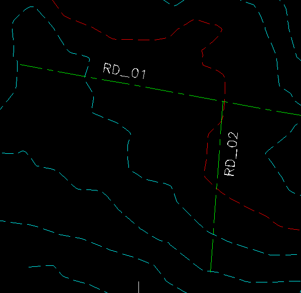 RD_01 and RD_02
In the project tree, highlight Roads and right-click and choose Add
Road.
After picking the Add button, the Add
Road dialog box provides two methods for adding a Road to
the Network. Pick the Screen Pick Polyline
button.
Specify Method to Use to Add
Road
The prompts then switch to the Command: line where you are prompted
to Select Centerline Polyline in the drawing. At the next
prompt, pick the Assign Centerline File to
Polyline button and set the path and filename for the
new Centerline (.CL) file.
Set Centerline Dialog Box
Immediately after creating the new Centerline file, the
Profile to Use file dialog box is displayed. In
this box, you must set the path and filename for the proposed
Profile (.PRO) file for the Road. By default, the new Profile
(.PRO) file is named the same as the Centerline (.CL) file.
Profile to Use File Dialog Box
After specifying the Centerline (.CL) and Profile (.PRO) files for
the Road, the Edit Road dialog box is displayed.
The only other Required Input
File is a Template (.TPL) file. Pick the
Template button to browse to and select the
desired Template file.
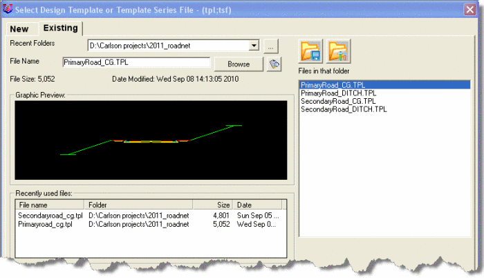 Select Template (.TPL) file Dialog
Box
Select Template (.TPL) file Dialog
Box
The Edit Road
dialog box serves as the "manager" for all files relating to the
specific Road. The Edit button in the Road
Name area of the Road Network: Task Pane
also displays the Edit Road dialog box.
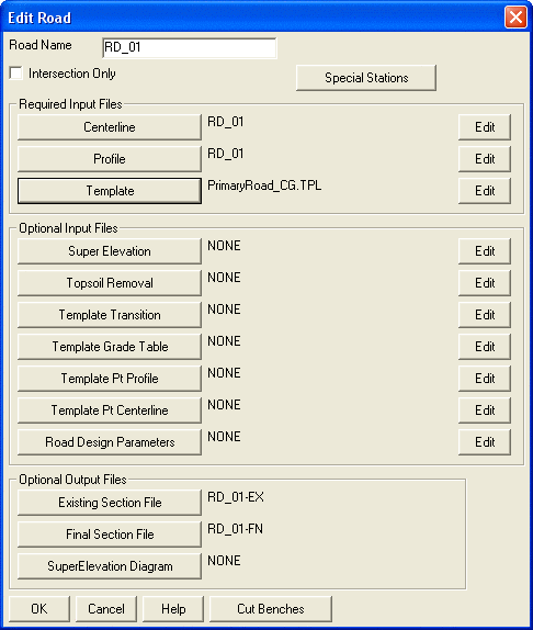 Edit Road Dialog Box
Pick the Edit button to the right of the
Profile button to open the Road Profile
Editor.
Input-Edit Road Profile Editor
In Carlson's Road Network feature, the initial
design Profile is automatically generated and has only a starting
and ending PVI - with the elevation at both ends tying into
existing ground. The movement of the crosshairs is locked to the
design Profile. The initial PVIs can be seen in the
profile-grid-view where the existing ground Profile is shown in red
and the design Profile in white. The initial PVIs are shown in the
table-view with the "PVI Description" indicating the PVI elevation
is tied to the "TARGET-SURFACE" (existing ground).
Pick the Add PVI button to create a new
PVI by screen-picking a point in the profile-grid-view at the top.
After picking the Add PVI button, the New
PVI dialog box is displayed.
New PVI Dialog Box
Enter a length for a vertical curve or change other settings as
desired and then pick the OK button. Repeat
as needed for additional PVIs and vertical curves.
Input-Edit Road Profile Editor
Pick the Show Sections button at the
bottom of the Road Profile Editor to display a
Section View of the Road. Moving your crosshairs
along the design Profile dynamically updates the Section
View.
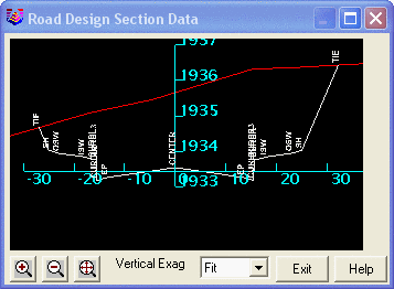 Section Viewer
When the Section View window is open and active,
the Road Profile Editor also remains open and
active. If you position the Road Profile Editor
and the Section View window so that the drawing
view of the Road is unobscured, you can move your crosshairs along
the design Profile and have a dynamic design environment allowing
you to see the plan-, profile- and section-views at one time.
Additionally, when the Section View window is
open, the notes at the top of the profile-grid-view include the
"Cut" and "Fill" end-area at the current station along with the
"Cut" and "Fill" volume for the entire Road. These calculations are
dynamic and will update if changes are made to the design
Profile.
Road Profile View and Section Viewer with
Station Indicator in Drawing
Pick the Exit button to close the
Section Viewer and then pick the
Save button in the Road Profile
Editor to save changes to the Profile (.PRO) file.
Pick the Exit button to close the
Road Profile Editor..
Repeat the steps above to define additional Roads in the
Network.
See Road Network: Adding and
Editing Roads if you need additional assistance.
Step 3: Adding and Editing Intersections
After Adding the next Road, the Road Network
command recognizes the creation of an Intersection and the Primary
and Secondary Roads are displayed in the
Intersection area of the project tree.
Select the Intersection, right-click and pick the Edit
Intersection function to display the
Settings tab of the Edit Intersection dialog
box. Make changes as needed.
Note: Changes made here apply to all Corners of the
Intersection.
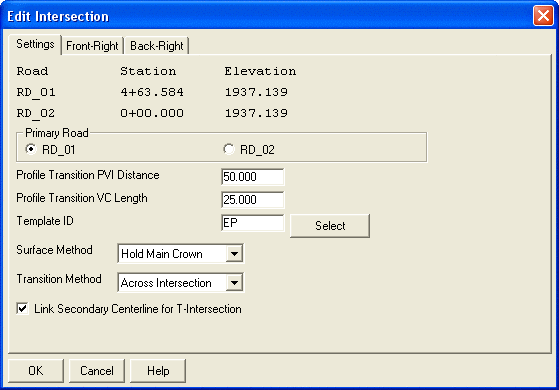 The Settings Tab of the Edit Intersection
Dialog Box
The Settings Tab of the Edit Intersection
Dialog Box
Or, you can switch to one of the Corner tabs -
Front-Right, Back-Right, Front-Left,
Back-Left to make changes to only one Corner of
the Intersection.
One of the "Corner" Tabs of the Edit
Intersection Dialog Box
Pick the OK button to close the
Edit Intersection box and save changes.
See Road Network:
Adding and Editing Intersections if you need
additional assistance.
Step 4: Adding and Editing Cul-de-Sacs
Pick the Add button in the
Cul-de-Sac area of the Road Network Task Pane to display
a dialog box listing the Roads in the Network and prompting you to
Select Road for Cul-de-Sac.
Select Road for Cul-de-Sac
After choosing the Road and picking the OK button,
the Edit Cul-de-Sac
dialog box is displayed. At a minimum, you must enter a
Cul-de-Sac Radius and Fillet
Radius to define the Cul-de-Sac.
Edit Cul-de-Sac Dialog
Box
Pick the OK button to close the
Edit Cul-de-Sac box and save changes.
See Road Network: Adding
and Editing Cul-de-Sacs if you need additional
assistance.
Step 5: Save, Process and View the Road Network
Pick the Save button on the Road Network Task Pane to
Save the Road Network (.RDN) file.
Then, pick the Process button on the
Road Network Task Pane to
calculate the road design and perform the functions specified in
Road Network Output
Options. The resulting contours and breaklines are
shown below.
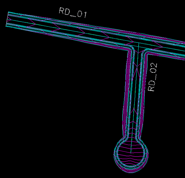 Contours and Breaklines After Processing
Road Network
Contours and Breaklines After Processing
Road Network
The elevated breaklines and contours can now be viewed using the
3D Viewer Window command as shown below.
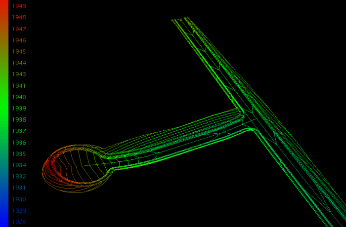 Breaklines and Contours as Seen in the 3D
Viewer Window
Breaklines and Contours as Seen in the 3D
Viewer Window
Or, use the Surface 3D Viewer command to view the
Surface (.TIN) file as shown below.
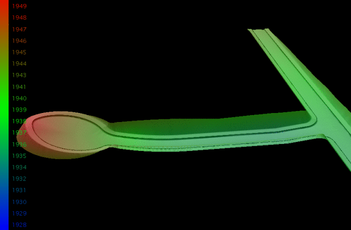 Surface (.TIN) File as Seen in the Surface
3D Viewer
Surface (.TIN) File as Seen in the Surface
3D Viewer
Or, use the Surface 3D Flyover command to drive
the Surface (.TIN) file as shown below.
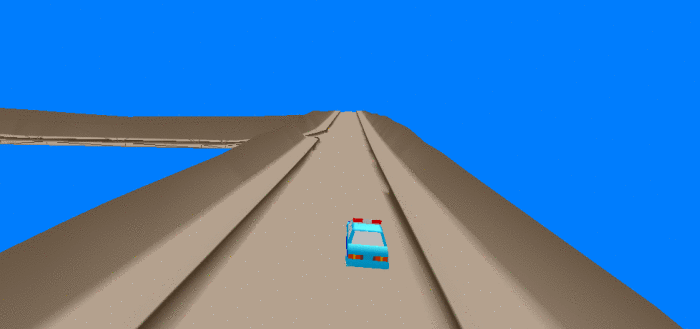 Surface (.TIN) File in the Surface 3D
Flyover Command
Surface (.TIN) File in the Surface 3D
Flyover Command
Step 6: Reports
Pick the Report button on the
Road Network Task Pane. Then, pick the
Output Processing button to display the
report. This report displays the cut/fill and material quantities
for each Road, Intersection and Cul-de-Sac of the Road Network.
Road Network Output Processing
Report
Repeat this step but, this time, pick the Input Data
Files button to display the report. This report
displays all of the user-specified design files associated with the
Road Network. For this report, you are given the option of
reporting only the filename or both the path and filename.
Road Network Input Data Files
Report
Step 7: Additional Settings and Tools in the Road Network
Draw Triangulation Faces with Color and View in 3D Viewer
Window
Pick the Settings button on the
Road Network Task Pane and then pick the
Output Options tab. Now, pick the
Setup button next to Triangulate and
Contour to open the Triangulate and Contour from
Road Network dialog box.
Select the Draw Triangulation Faces
option and then pick the Set
Colors/Layers buttons to display the Road
Color Settings dialog box (shown below). The color of the
faces can be set either by using the Template IDs defined in
the Template (.TPL) file or using a color range based on the "Cut
& Fill Depths".
Set Road Colors In the "Triangulate and
Contour From Road Network" Dialog Box
Pick the Exit button to close the
Road Color Settings box and then pick the
OK button twice to exit both the
Triangulate and Contour and Road Network
Settings dialog boxes.
Pick the Save button on the Road Network Task Pane to
Save the Road Network (.RDN) file.
Then, pick the Process button on the
Road Network Task Pane to
calculate the road design and perform the functions specified in
Road Network Output
Options The image below shows only the Triangulation
Faces after Processing. 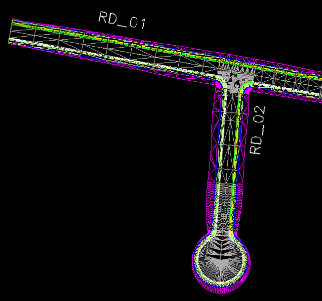
Triangulation Faces with
Color After Processing Road Network
The elevated Triangulated Faces can now be viewed using the
3D Viewer Window command as shown below.
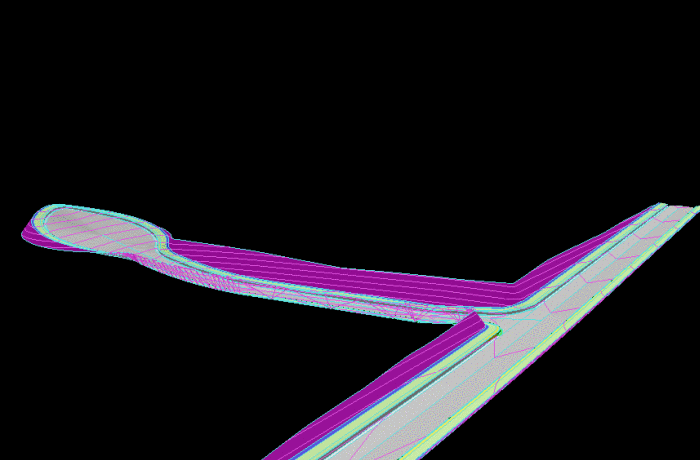 Contours and Triangulation Faces with
Color in the 3D Viewer Window
Contours and Triangulation Faces with
Color in the 3D Viewer Window
Merge Road with Existing
Pick the Settings button on the
Road Network Task Pane and then pick the
Output Options tab. Select the
Merge Road with Existing option and then
pick the Set button to set the path and
filename of a 3rd Surface (.TIN) file to be created by combining
the design Surface file and the Existing Ground Surface file.
Pick the OK button to close Road
Network Settings.
Pick the Save button on the Road Network Task Pane to
Save the Road Network (.RDN) file.
Then, pick the Process button on the
Road Network Task Pane to
calculate the road design and perform the functions specified in
Road Network Output
Options
The combined Surface (.TIN) file can now be viewed using the
Surface 3D Viewer command as shown below.
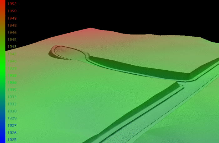 Merged Existing Ground and Road Surfaces in
3D Surface Viewer Window
Merged Existing Ground and Road Surfaces in
3D Surface Viewer Window
Add Knuckle Intersection
Using the steps outlined in 2 Add Roads to the
Network above, Add two more Roads to the Network.
 RD_03 and RD_04
Upon adding the Roads, the new Intersections are automatically
added to the Intersection area of the Road
Network Task Pane.
To create a "Knuckle" style Intersection between RD_03 and RD_04,
select the RD_03 (Primary)/ End:RD_04
(Secondary) Intersection in the project tree and then
right-click and pick the Edit Intersection
function to display the Settings tab of the
Edit Intersection
dialog box. Pick one of the "Corner" tabs
of the Edit Intersection dialog box. Select
the Use Knuckle option and enter a
Main Radius and Fillet Radius
value for the Knuckle Intersection.
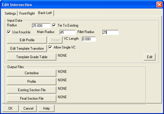 A "Corner" Tab of the Edit Intersection
Dialog Box
A "Corner" Tab of the Edit Intersection
Dialog Box
Pick the OK button to close Edit
Intersection.
Pick the Save button on the Road Network Task Pane to
Save the Road Network (.RDN) file.
Then, pick the Process button on the
Road Network Task Pane to
calculate the road design and perform the functions specified in
Road Network Output
Options. The resulting contours and breaklines are
shown below.
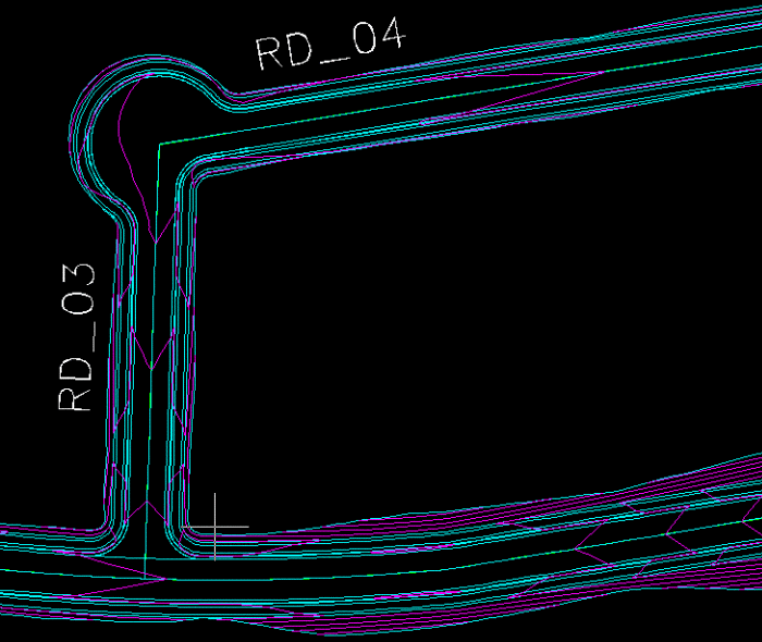 Contours and Breaklines Through a "Knuckle"
Style Intersection
Contours and Breaklines Through a "Knuckle"
Style Intersection
Workflow Example 2
Step 1: Start New Road Network
Start the Road network command. If you have previously run Road
Network with the current drawing, the Road Network docked dialog
will open with the last Road Network (.RDN) file you worked with.
If this happens, but you prefer to create a new Road Network (.RDN)
file, click the Load/New button at the bottom of the Road Network
docked dialog.
Step 2: Add Roads
Back in the main dialog, click "Add" in the upper left "Road
Name" portion, and identify all of the main road and secondary
(intersecting) road centerlines. For this example, we will start by
identifying North Road and East Road as the main roads and Paris
Boulevard as the first secondary road. Note that centerlines
may be picked as polylines or loaded as centerline files. All
centerlines (horizontal alignments) must have, at minimum, an
associated profile (vertical alignment) and an associated template.
In the Road name dialog portion, select a road and click Edit to
review the files. Note that by selecting Paris Boulevard and East
Road, the program automatically detects the first intersect.
As you follow the design below, you will see that we follow the
hierarchy of the road precedence as outlined in the graphics.
At every intersection, there needs to be a primary controlling road
(template cross slopes are held) and secondary adjusting road
(centerline profile adjusts to template of primary road at some
transition distance).
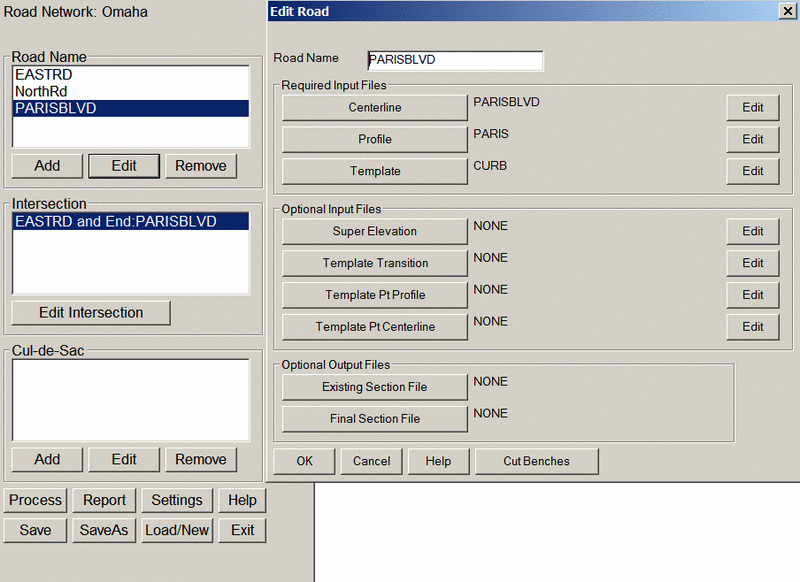
Step 3: Process, Review and Add more
Click Process to compute the design. With the
Triangulation option enabled under the "Settings" dialog, the
program will Triangulate and Contour and create the drawing shown
below. If you edit any road feature or dialog entry and click
Process again, the program automatically clears the last
Triangulate and Contour drawing and creates a new final design
drawing. In this way, you can trial-and-error your design for all
roads, or build the design in stages.
Viewing the file in the 3D Viewer
Window comman
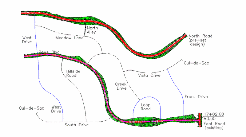
d
with a 4.0 vertical exaggeration, you can even see how the
curb-and-gutter Paris Boulevard ends abruptly as it transitions to
the roadside ditch template of East Road.
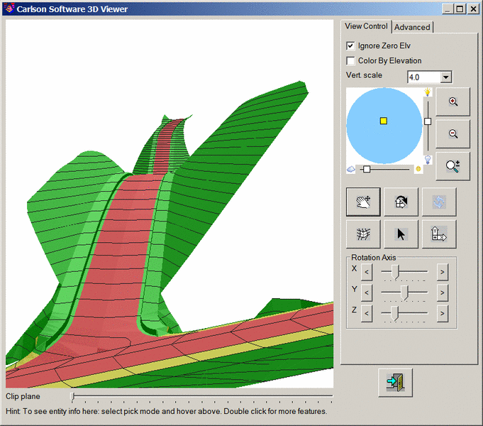
Next we can review the effect of adding Front Drive, Loop Road
and West Drive into the equation. If you click Edit after adding
Loop Road as above, you have the option to change any aspect of the
centerline, profile or template file, and you can add optional
files such as road width change files and superelevation files. For
example, if you choose to edit the profile, the program derives the
existing grade from the existing surface triangulation file
specified in Settings, and you are able to design graphically and
interactively as shown:
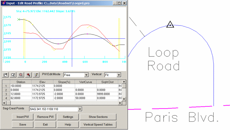
You can also more closely analyze the intersections of any
road. If you select the intersection at ParisBlvd and
Start:LoopRd, you obtain the multi-tab dialog:
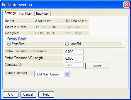 Since we do not have a crossing
intersection, we only obtain a "Front-Left" tab and a "Back-Left"
tab, left being the left side of the primary road (Paris) and front
being the first "curve return" treatment on the outside of the loop
and back being the second "curve return" treatment on the inside of
the loop. If this was a crossing intersection, you would have
2 more tabs in the dialog: "Front-Right" and
"Back-Right".
Since we do not have a crossing
intersection, we only obtain a "Front-Left" tab and a "Back-Left"
tab, left being the left side of the primary road (Paris) and front
being the first "curve return" treatment on the outside of the loop
and back being the second "curve return" treatment on the inside of
the loop. If this was a crossing intersection, you would have
2 more tabs in the dialog: "Front-Right" and
"Back-Right".
Completing West Drive, Front Drive and South Drive leads to the
following plan view and 3D view. Clicking Add within the Cul-de-Sac
portion of the docked dialog enables you to specify at cul-de-sac
at the end of South Drive.
Clicking Process now produces the following:
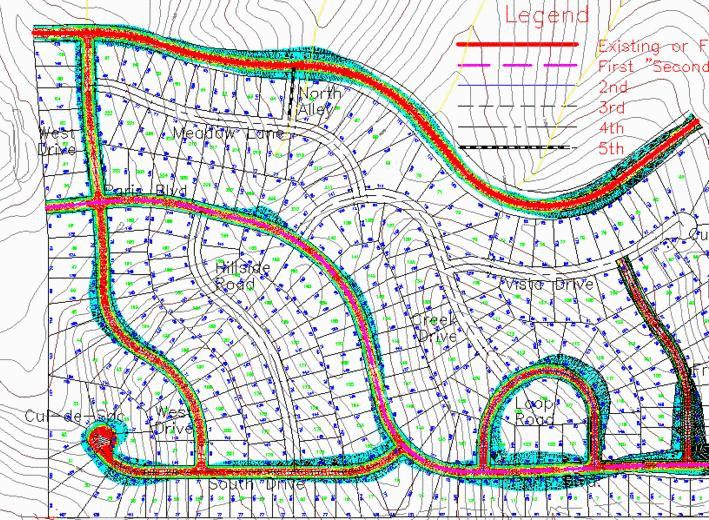
A close-up view of the cul-de-sac, in 3D, reveals the detail of
the design, showing a raised "fold" due to no vertical curve
transition at the projected high point at the back of the
cul-de-sac:
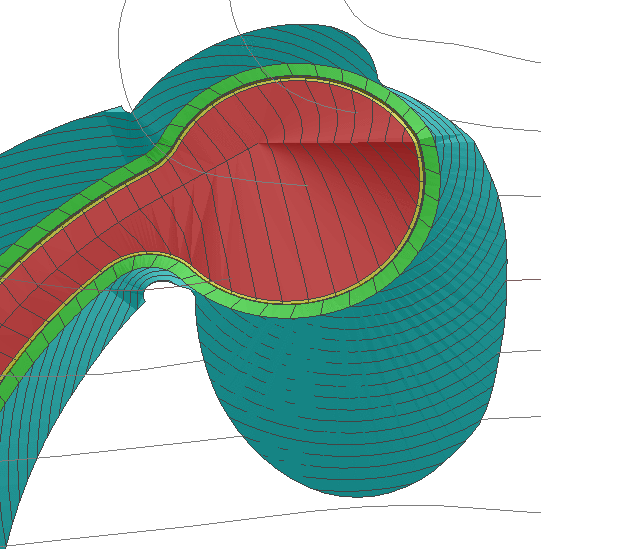
This dimple effect can easily be eliminated by lowering the
elevation of the "PVI" at the projected intersect point in the back
of the cul-de-sac, and by adding a vertical curve transition of,
say 50'. This is done by highlighting the South Drive
Cul-de-Sac and clicking Edit.
Clicking Edit on the selected SouthDr at End cul-de-sac leads to
this dialog:
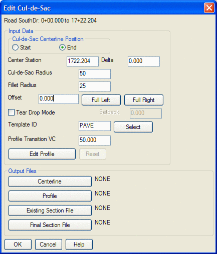
The first thing we do is change the Profile Transition VC from
0.0 to 50.0, as shown. Then we need to click Edit Profile to
lower the profile at the back of the cul-de-sac. This profile
refers to the edge-of-pavement grade.
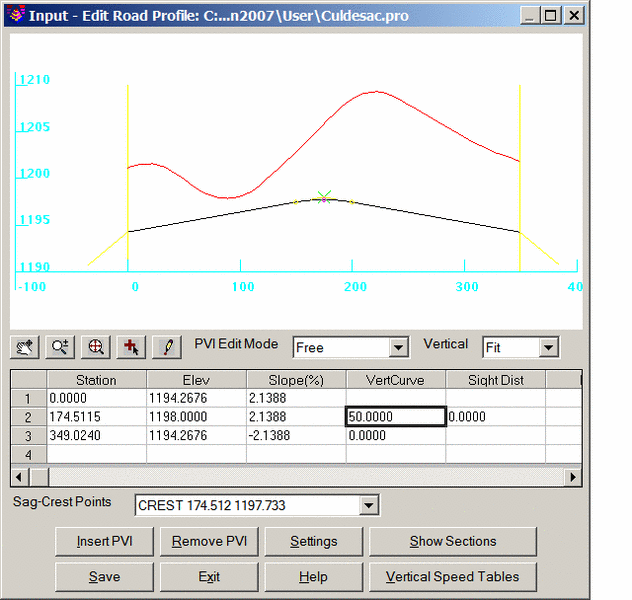
Now, after clicking Process, the cul-de-sac has a better
design:
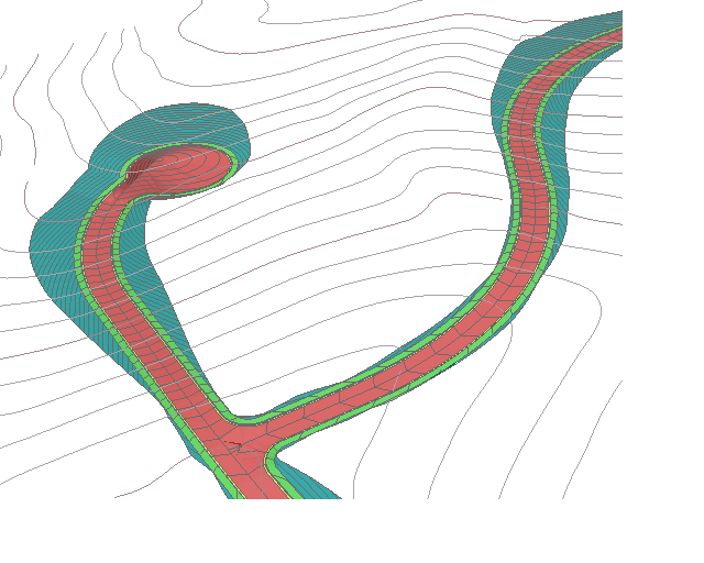
Pulldown Menu Location: Roads → Road Network
Keyboard Command: roadnet
Prerequisite: Existing Ground Surface (.TIN) file, Template
(.TPL) file