The Comparison Surface button is used to enter a
three-dimensional surface file (.flt or.tin) for determination of
cut and fill volume differences between the comparison surface and
the GeoFluv landform design that the user has made.
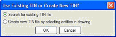
When the user clicks on the Comparison Surface button, the Use
Existing TIN or Create New TIN? Pop-up dialog box appears to give
the user the options, by clicking on radio buttons, for entering a
3-D surface file. By clicking OK when the radio button
is on Search for existing TIN file, the user can browse through
existing files to select the file to import, or select the file
from a list of recently used files. When the user highlights
the desired file and clicks the Open button, the file name appears
below the Comparison Surface button and the user is ready to begin
the Update Cut / Fill command.
Alternatively, the user can click the radio button for Create new
TIN file by selecting entities in the drawing. When the user
selects this option and clicks OK, the cursor changes to a
selection box that the user can use to define an area with a
crossing window. (Note: it is very important that this area
encompass the entire GeoFluv project .tin surface. Areas
outside the work area that are the same in both the comparison
surface and the GeoFluv design will not affect the volume balance
so the user does not have to be concerned with defining a slightly
larger area.) After defining the new .tin area, the user hits
the Enter key and the Select Comparison Surface TIN file -
(.tin;.flt) dialog box appears.
The user can choose an existing .tin file by browsing folders or
choosing from recently used files, or click on the New tab to
create the new .tin file. The user can click on the New tab,
enter a name for the new .tin file, and click OK.
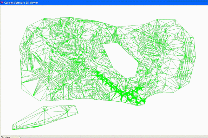
The Carlson Software 3D Viewer window will appear showing the .tin
for the area that the user has defined. The user can rotate,
fill in the .tin triangles, etc. to preview the .tin to be sure
that it is satisfactory, i.e., no unwanted holes, elevation spikes,
etc. When the user is satisfied that the .tin correctly
represents the comparison surface, the user closes the 3D viewer
window and the command prompt line reads Select Inclusion
Polylines.
The Select Inclusion Polylines option allows the user to define
area boundaries for use in the Cut / Fill balance with
polylines. By default Natural Regrade will use the GeoFluv
boundary polyline as an inclusion boundary to compare against the
specified Comparison Surface. Inclusion area boundaries are
useful if the user wants to add an adjacent stockpile volume to the
calculations, for example. The user clicks on any additional
desired inclusion area polylines, including the GeoFluv boundary
polyline as needed, that Natural Regrade will use in the
calculation. If no inclusion boundary lines other than the
GeoFluv boundary are needed, or when all selections are made, the
user can hit Enter and is prompted to select Exclusion
polylines.
Exclusion polylines are the inverse of inclusion polylines.
They can be used to exclude an area like a homesite that is
surrounded by the GeoFluv project. If no exclusion boundary
lines are needed, or when all selections are made, the user can hit
Enter and is prompted to select Exclusion polylines. Natural
Regrade will then display the number of inclusion and exclusion
polylines that will be used in the cut / fill calculation.
The user is then ready to proceed to the Update Cut / Fill button
to make the calculation.
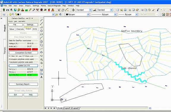
In the example, the user has selected two inclusion boundaries,
the GeoFluv boundary and a boundary line around a stockpile
southwest of the GeoFluv boundary, and one exclusion boundary on
top of a ridge near the middle of the GeoFluv design.
The Update Cut / Fill button makes the calculation of the cut
and fill needed to make the GeoFluv design from the comparison
surface that the user has specified.
When the user clicks on the Update Cut / Fill button, the Carlson
Software 3D Viewer window appears showing the .tin that will result
from the user's specified file and any inclusion and exclusion
boundaries. This helps the user to quickly verify that the
specified areas are as desired. The user may also find it
helpful to use the 3D Viewer's Toggle shading of surfaces button to
fill in the triangle mesh spaces when inspecting the .tin.
When the user closes the 3D viewer, the calculation results are
displayed below the Update Cut / Fill button.
The calculation respects any inclusion and exclusion areas that the
user has specified. When the result is within the balance
range that the user specified in the Natural Regrade Global
Settings (accessed via the Settings button), the Cut / Fill (%) is
highlighted in green to give the user quick feedback; conversely,
if the result is outside the user-specified range the result is
highlighted in red.