This is an alternative version of Edit/Create Sewer Structure
for the design of sanitary and utility networks. A sanitary or
utility network is generally made up of pipes and structures. There
may be more than one pipe entering a structure, but only one can
exit. The network type is set in the Sewer Network Settings dialog,
and the default type is storm sewer. When you run Edit/Create Sewer
Structure, the program performs differently based on the network
type. If you work on a storm sewer network, please refer to the
documentation on the Edit/Create Sewer Structure.
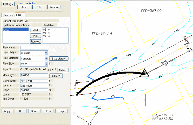
This command construct a graphical representation of a pipe
network in active drawing, which contains all your design data,
such as pipe and structure data. The following is an network
example. The Edit/Create Sanitary/Utility Structure dock dialog is
on the left, while the network plan view in the active drawing is
on the right with current structure and pipe highlighted. When you
modify the edit fields on the dock dialog and click on Apply
button, the network plan view will be updated automatically.
Furthermore, you are allowed to work on the active drawing while
the dock dialog is open. This command doesn't perform hydrology
calculation, so no flow data is needed.
|
|
| Edit/Create Sanitary/Utility
Structure Dialog and Dynamic Editing in the Active Design
Drawing |
First set up the working environment by running command Sewer Network Settings under Network > Sewer Network Setup menu. Then select Edit/Create Sewer Structure. If you are creating a sewer structure, pick a location in the plan view where you want to locate the structure, otherwise click on an existing structure symbol. After a structure has been located, the dock dialog displays, and the current structure symbol is highlighted in the drawing. Following is an example of the dock dialog.
|
| Edit/Create Sewer
Structure |
This dialog window has two tabs, Structure and Pipe, which are
used to enter structure and pipe parameters. The following is the
description of the functionalities of the buttons for designing
sanitary/utility network.
Settings: This function performs as same as the Sewer
Network Settings command except for the generate settings of
setting up the network file and surface file etc. Please refer to
the documentation on Sewer Network Settings.
Add: Adds a new structure to the network at the location you pick in the plan view. The just created structure will become the active structure for editing.
Edit: This function allows you to pick an existing structure symbol in the plan view to make the structure active for editing.
Remove: This function removes the structure that you pick, and also removes the corresponding pipes and then reconstruct the network.
Apply: Save the changes of the network.
Up: Moves to the upstream structure and makes it active.
Down: Moves to the downstream structure and makes it active.
Close: Quit the sewer network dock dialog.
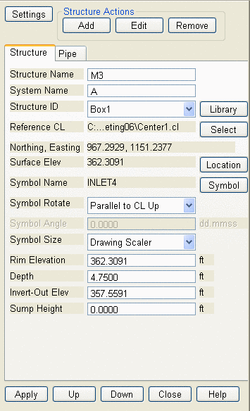
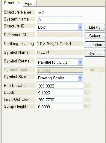
2. StructureThe structure data is entered through the Structure tab.
|
| Sanitary/Utility Network Edit
Structure |
Structure Name: An identical name of the structure in the network.
System Name: A name for current network. All the structures in the same network have the same system name.
Structure ID: This is the ID of a predefined structure in the structure library. The Library button next to it allows you to select or define a sewer structure in the structure library. Once you select the structure, the dimension of the structure are retrieved from the library. Please refer to the documentation of the Sewer Structure Library for details.
Reference CL: The reference centerline is used to locate
the structure by station/offset of the centerline points, and align
the structure symbol in the graphic. The Select button
allows you to select a centerline from either a centerline file or
a polyline.
Location: This button allows to relocate the structure by
pick a position in the drawing.
Symbol Name: This is the name of the symbol that represents the structure in the network plan view. The Symbol button allows you to select a symbol from a list of symbols.
Symbol Rotate: There are 10 options to rotate the structure symbol for displaying in the drawing.
Symbol Angle: When the Symbol Rotate value is set to Enter Azimuth Angle, this edit field is enabled for entering an angle.
Symbol Size: Three options to determine the size of the structure symbol.
Rim Elevation: The rim elevation for the structure, it's usually the surface elevation.
Depth: The distance between the rim elevation and the base elevation of the structure.
Invert-Out Elev: The invert elevation of the pipe that exits the structure.
Sump Height: The distance between the base elevation and
the invert-out elevation.
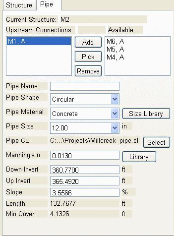
The pipe data is entered through the pipe tab. The Downstream/Upstream list contains the connection that exits the structure or the connections that enter the structure, depending on the design direction. The Available list contains all the structures that are not connected to the current structure, i.e. the potential structures that can be connected to the current structure. There is two ways to add a connection. The first one is clicking on the Add button to connect the highlighted structure in the Available list to the current structure. The other one is clicking on the Pick button and then select a structure symbol in the plan view to connect it. If the connection is unable to be performed, a warning massage pops up. By selecting the available structure to Add or Pick the Pipe Connection Wizard dialog will open to allow the user to visualize the connection to be made. See the following section for more information on the Connection Pipe Wizard. The Remove button allows you to remove the highlighted connection from the Downstream/Upstream list.
|
| Sewer Network Edit Pipe |
Pipe Name: An identical
name of the pipe in the network.
Pipe Shape: The pipes
can have four different cross-sectional shapes: circular, box,
horizontal ellipse and vertical ellipse.
Pipe Material: There are nine material options.
Pipe Size: The value can be chosen from a list of pipe
sizes stored in the size library.
Pipe Size Library: This button allows you to store
commonly used pipe sizes. Please refer to the documentation on the
Pipe Size Library for details.
Pipe CL: This option allows you to design a non-straight pipe. The pipe centerline should start from one structure and end at the other exactly. If you change the location of one of the structures, the centerline would be deserted and the pipe would become straight.
Manning's n: The Manning's n coefficient is used to
calculate the friction loss of the pipe. The Library button
allows you to select a Manning's' n value. Please refer to the
documentation on the Manning's N Library for details.
Down Invert/Up
Invert: They are the downstream invert and upstream invert
elevations of the pipe.
Slope: Pipe slope.
Min. Cover: The minimum
distance from the surface elevation to the crown elevation all
along the pipe, is calculated automatically.
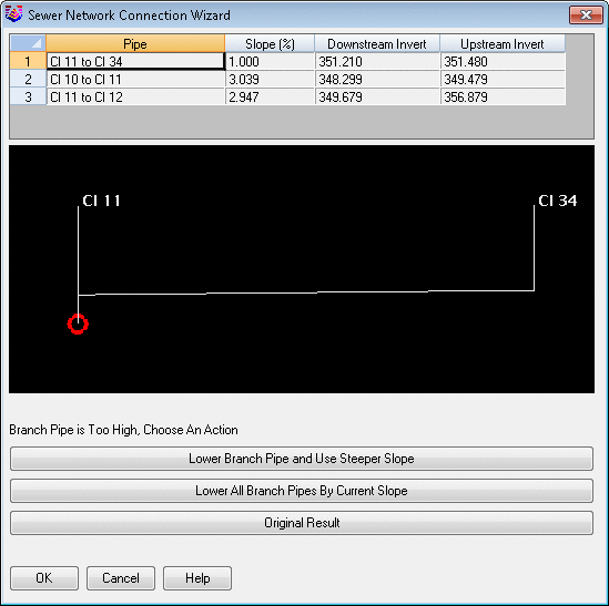
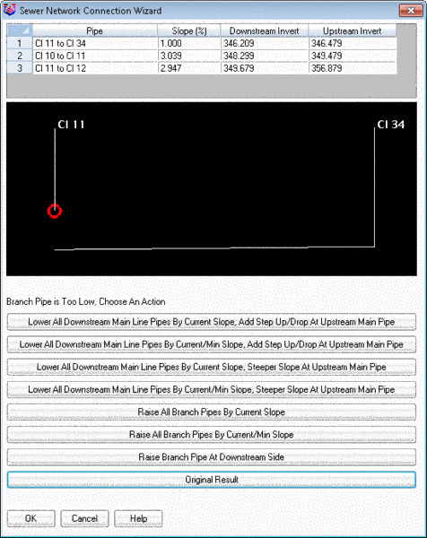
Selecting the available structure to Add or Pick
the Pipe Connection Wizard dialog will open to allow the
user to visualize the connection to be made. If the normal slope
based from the Sewer Network Settings file CAN be
created the following dialog box will appear.
 .
.Select sewer structure to edit: pick a manhole
symbol
Sewer Structure Data dialog: Fill in values
Pulldown Menu Location: network > Edit/Create Sewer
Structure
Keyboard Command: editswr/putswr
Prerequisite: a sewer file (.SEW), a surface file (.TIN,
.GRD, .FLT)