 Keyboard Command: BLKMODEL
Pull-down Menu Location: Block Model
Prerequisite: Drillholes with a bed name, and variable quality values that can be vertically modeled.
This is one of the initial commands to begin using
the block modeling features of Carlson. It uses similar grid logic,
for location and resolution in the X and Y. It will take bed and
subdivide it into vertical divisions. This can be applied to
stratified deposits, or ore based geology, where it is not
stratified, such as limestone or copper, gold and silver. In these
ore type cases, the strata or bed name could be just rock, or
limestone all the way down the hole. It would then look at just the
quality being modeled as the variable. The program takes this
interval, makes a roof and a floor and divides it up equally into
the number of vertical divisions specified, or at an elevation
"lift", where the top and bottom elevations are specified, and the
block height calculated based on the number of divisions.
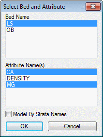
The first dialog brings up the Select Bed and
Attribute screen. One bed name must be selected, and one or more
attributes selected. If there are no Bed names in the drillholes,
then select the Model By Strata Names box to use just Strata
names.
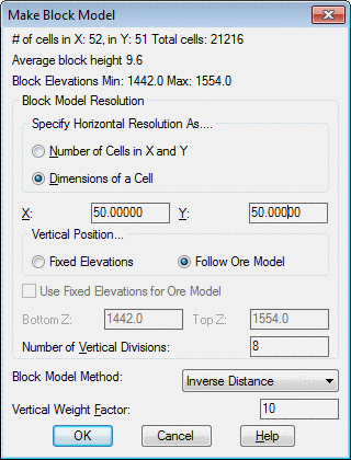
 The next screen, Make Block Model,
is for dimension and modeling settings. The number of cells in the
X and Y direction are shown at the top. The total number of cells
in plan view is shown next. The block height is determined by the
Number of Vertical Divisions and Vertical Position settings. There
are two options to determine the Vertical Position. The first one
is by Fixed Elevations. This will activate the Bottom Z and Top Z
windows where the roof and floor for the block model are entered.
The Follow Ore Model makes the top and bottom of the block model
follow the top and bottom elevations of the bed being processed.
The Crop No Grade option sets the top and bottom of the block model
to the limits of where the model has grade defined by the Grade
Parameter File. When using this option, the program prompts for the
.GPF file to process. The Use Fixed Elevations for Ore Model
controls how the attributes are interpolated for the Fixed
Elevations mode. When this option is on, the attributes are
calculated at the fixed elevations. When this option is off, the
attributes are calculated within the elevation range of the bed and
then interpolated to fit within the fixed elevations. The Number of
Vertical Divisions controls the number of block model data points
between the top and bottom of the block model.
The next screen, Make Block Model,
is for dimension and modeling settings. The number of cells in the
X and Y direction are shown at the top. The total number of cells
in plan view is shown next. The block height is determined by the
Number of Vertical Divisions and Vertical Position settings. There
are two options to determine the Vertical Position. The first one
is by Fixed Elevations. This will activate the Bottom Z and Top Z
windows where the roof and floor for the block model are entered.
The Follow Ore Model makes the top and bottom of the block model
follow the top and bottom elevations of the bed being processed.
The Crop No Grade option sets the top and bottom of the block model
to the limits of where the model has grade defined by the Grade
Parameter File. When using this option, the program prompts for the
.GPF file to process. The Use Fixed Elevations for Ore Model
controls how the attributes are interpolated for the Fixed
Elevations mode. When this option is on, the attributes are
calculated at the fixed elevations. When this option is off, the
attributes are calculated within the elevation range of the bed and
then interpolated to fit within the fixed elevations. The Number of
Vertical Divisions controls the number of block model data points
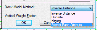
between the top and bottom of the block model.Discrete is a method to model parameters such as
color. It will carry one color 1/2 way over to the next drillhole,
then switch to the other color. This way, there is now blending of
colors, if color1 is a 2 in one drillhole and color2 is a 4 in the
next drillhole, it will not blend them to a "3" in the middle. It
models 2, and then switches to 4 at the halfway point.
The kriging option will require additional
information to calculate. The below dialog will appear before the
block model is created.

Minimum: This value sets the minimum attribute value to process when creating the block model.
Maximum: This value sets the maximum attribute value to process when creating the block model.
Min Points to Use: This value sets the minimum number of points to use when creating the block model.
Max Points to Use: This values the maximum number of points to use when creating the block model.
Search Radius X, Y, Z: These three values set the search radius of points to use when creating each block in the model. These values will determine the maximum distance of influence of each data point used to create the model.
Rotation Angle 1:
Rotation Angle 2:
Rotation Angle 3:
Output Estimation Variance: This option will output a __ file that estimates the variance of the
On the right side of the dialog are the variogram parameters. These values may be loaded from a preivously calculated variogram. Detailed information on each of these parameters is provided under the Calculate Variogram command in the help manual.
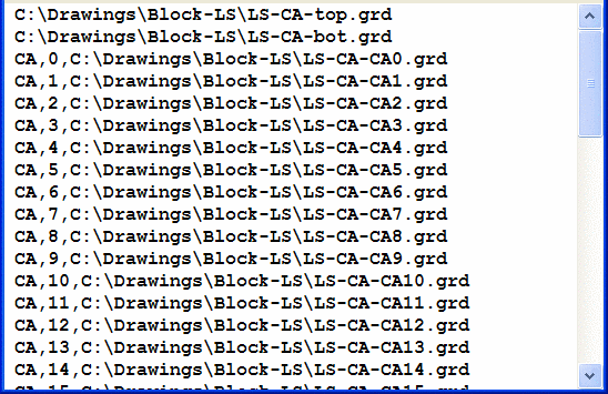
After the routine is finished calculating, it creates a *.BLK file. This file can be viewed in a text editor to see what it contains, as shown here. Basically, it shows the roof and floor, the quality attribute name and the file paths of each level of the block qualities.
Keyboard Command: BLKMODEL
Pull-down Menu Location: Block Model
Prerequisite: Drillholes with a bed name, and variable
quality values that can be vertically modeled.