 The
Coordinate File at the top of the dialog shows the current
file which can be changed with the Set button.
The
Coordinate File at the top of the dialog shows the current
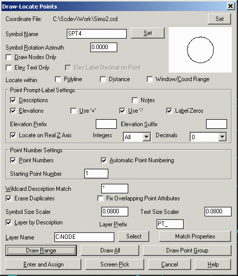
file which can be changed with the Set button.The Draw-Locate Points dialog box allows you to insert either
new or existing points into the drawing. You can create new points
either by picking points on the screen, or by entering northing and
easting coordinates. You can also place existing points by entering
point numbers which reference the current coordinate file. You are
prompted to choose a coordinate file if no coordinate file is
current.
The
Coordinate File at the top of the dialog shows the current
file which can be changed with the Set button.
The name of the symbol file is displayed in Symbol Name. You can choose a different symbol by clicking Select. The selected point symbol is displayed on the right.
Symbol Rotation Azimuth is the rotation angle that is used for the point symbols. This angle is used in a counter-clockwise direction relative to the current twist screen.
Layer by Description inserts the points in the layer named by the point description. Using Layer by Description organizes the points by description and allows for layer management. For example, you can use the Isolate Layers command to show only points on a certain layer. If you include an invalid layer character in the description, the layer name stops at the bad character. A point description of "UP / 105" would use layer "UP", for example. The Layer Prefix is added to the beginning of the layer name. For example, a Layer Prefix of "PT_" and a point with the description "EP" would use the layer "PT_EP". Layer Prefix is optional. It allows all the point layers to be grouped.
Draw Nodes Only inserts only a point entity (the node) and not the point block and symbol. This option is most useful when you have a lot of points to insert, because inserting only the nodes is faster than inserting nodes with the point block and symbol. Commands such as Triangulate & Contour and Make 3D Grid File can use these points, and do not need the point block and symbol.
Selecting Elev Text Only draws text of the point elevation without the point block, symbol, or node. The decimal place of elevation text is placed at the northing and easting point location.
Locate within Polyline inserts only the points that are inside a closed inclusion polyline. The command prompts you to select a closed inclusion polyline and as well as an optional exclusion polyline. All the points in the current coordinate file are checked. Any points that are located within the inclusion polyline and outside the exclusion polyline are drawn.
Locate within Distance inserts only the points that are within a specified distance from a reference point. The command asks you for the reference point and the search distance. All the points in the current coordinate file are checked. Any points that are located within the search distance of the reference point are drawn.
Locate within Window/Coord Range inserts only the points
that are within the specified window or range of northing, easting,
and elevation. The command prompts for the minimum and maximum
northing, easting, and elevations. These values default to the
actual minimum and maximum in the coordinate file. Then the command
prompts for the point number range of points to check. The points
that fall in both the point number range and the coordinate range
are drawn.
Under Point Prompt-Label
Settings, you determine attributes for which you will be
prompted.
Descriptions determines whether you are prompted for descriptions for each point when creating new points. When you are placing both new and existing points, Descriptions determine whether this attribute is labeled with the point inserts.
Notes works with the note file (.not) associated with the current coordinate file. The note file contains unlimited point descriptions in addition to the fixed 32-character point descriptions in the coordinate file. When you create points with Notes on, the command will prompt for point notes to be stored with the point. When you draw existing points with Notes on, any notes for the points are drawn as text entities below the point description.
Elevations determines whether you are prompted for elevations for each point when creating new points. When you are placing both new and existing points, Elevations determine whether this attribute is labeled with the point inserts.
Use '+' labels the positive elevations with a leading '+'. For example, "+159.43".
Use '-' labels the negative elevations with a leading '-'.
Locate on Real Z Axis determines if the points are placed at their elevations or at zero elevation.
Label Zeros will label points with zero elevation when the Elevations option is on. Otherwise only points with nonzero elevation will be labeled.
Elevation Prefix/Suffix set the prefix and suffix labels to apply for the elevation labels.
Elevation Integers controls the number of digits to display to the left of the decimal point for the elevation label. The All setting will show the full elevation digits. The other settings allow you to limit the number of digits to display for the purpose of reducing the amount of space the elevation labels take up in the drawing. For example, if a site is in the 4000 foot elevation range, then this setting could be set to three digits (000) and an elevation of 4321 would be labeled as 321.
Elevation Decimals sets the number of decimals to the
right of the decimal places for the elevation labels.
Under Point Number Settings, you determine how points will be numbered.
Point Numbers determines whether the complete point block is drawn or just the symbol and node. When you create new points with Point Numbers off, no points are stored in the current coordinate file, and only the point symbol and node are drawn. When you draw existing points with Point Numbers off, the point attribute block is not drawn and only the point symbol and node are drawn.
Automatic Point Numbering applies to creating new points. With this option active, the command will use the Starting Point Number for the first new point. The next point number is automatically incremented. Before storing the point, the command checks whether the point number is used. If the point number is used and point protect is on (set in the Coordinate File Utilities command), then the command will prompt for another point number or to overwrite the point. With Automatic Point Numbering off, the command will prompt for the point numbers.
Determine how the points are to be displayed and in what layer.
With Wildcard match of pt description, you can display only points with specific descriptions. This can be thought of as a filter. For example, entering IP would display only points that are labeled with the description IP, or Iron Pin. The default is the asterisk (*). This will display all points regardless of description.
Layer Name allows you to designate a layer for the points
to be displayed. You can enter a new name, CLAYER, or choose an
existing layer by clicking Select Layer. Entry of CLAYER
selects the current layer. A Carlson Survey point consists of a
block insert with attributes, a point symbol, and a point entity.
The point entity is used for picking the point by OSNAP Node in
other commands. The block insert includes a point number,
elevation, and description. These attributes are in the PNTMARK,
PNTNO, PNTELEV, and PNTDESC layers. The points are also in an
overall layer as specified in this dialog box. This layer setup
allows you to freeze a group of points by the main layer name or
freeze point attributes for all the points in the drawing. For
example, freezing layer "PNTS" would freeze all the points in this
layer. Freezing layer "PNTELEV" would freeze the point elevation
attribute for all the points.
The Duplicates option
for Erase and Redraw will erase existing point entities that
match the point numbers currently being drawn. The Allow
Duplicates option will leave any existing point entities as the
specified points are drawn. The Draw Only New option will
only draw points that don't already exist in the drawing.
Fix Overlapping Point
Attributes will detect point number, elevation and
description attributes that overlap with other points. Rules can be
applied to rearrange the point attributes to avoid the overlaps. A
point overlap manager then steps through each overlap for review or
manually moving the attributes.
Symbol Size Scaler controls the size of the point symbol
and Text Size Scaler controls the size of the point
attribute labels. The scalers are multiplied by the Horizontal
Scale from Drawing Setup to set the size in drawing units.
Match Properties prompts to select an existing point
entity and then the program sets the settings in the dialog such as
layer and symbol to match the selected point.
Draw Range will draw existing points from the current coordinate file. The Draw Range button will prompt for the point numbers to draw.
Draw All will draw all the points in the coordinate file, and then zoom the extents of the display to show the points.
Draw Point Group will draw a point group with settings that are established in the Point Group Manager.
Enter and Assign can be used to create new points using
the point northing and easting. When a grid projection is defined
in Drawing Setup, then there is an option to enter the points using
latitude/longitude.
Screen Pick allows you to create points by picking the point coordinate on the screen. For example, you could set the Object Snap to EndPoint and pick the end point of a building polyline to create a point at the building corner.
To create a new
point:
Draw-Locate dialog
choose
Screen Pick
Pick point
to create: pick a
point
Select/<Enter Point Elevation <0.00>: Enter elevation
Press S to select text to set
elevation.
Enter Point Description <>: Enter
N: 5106.57 E:
4901.96 Z: 0.00
Enter/<Select text of elevation>: Select text
entity that defines elevation of point.
To locate a point in the coordinate file (point number 3 in this
example):
Draw-Locate
Point dialog choose Draw
Range
Point numbers to draw:
3
Points Drawn>
1
Locates point 3.
Point numbers to draw:
1-2
Points
Drawn> 2
Locates a range of points. From 1 to 2.
Point numbers to draw:
Enter
Keyboard Command: lpoint
Prerequisite: A CRD file and you may want to execute
Drawing Setup (see the Setting menu) to set the scale and
size.