Lesson 15: ESRI to Office to Field and Back
This lesson takes an ESRI geodatabase from ArcView into Carlson
Survey and then to Carlson SurvCE for data collection. Next the
data is taken from SurvCE into Carlson Survey and then back into
ArcView.
Step 1 (ESRI Geodatabase to DWG File):
ArcGIS Desktop has a routine to output a
geodatabase to a DWG file. The DWG file contains all the
information in a single file. It has the graphic geometry, feature
definitions and feature attribute data. The feature information is
stored in a format defined by ESRI called Mapping Specification for
DWG (MSD) using standard DWG entities and dictionary entries. In
this tutorial, we're going to use ArcView 9.3 to create the DWG
with MSD.
From the ArcToolbox, choose Conversion
Tools->To CAD->Export To CAD. If you need to bring up the
ArcToolbox, go to the ArcView->Window pull-down menu and pick
ArcToolbox.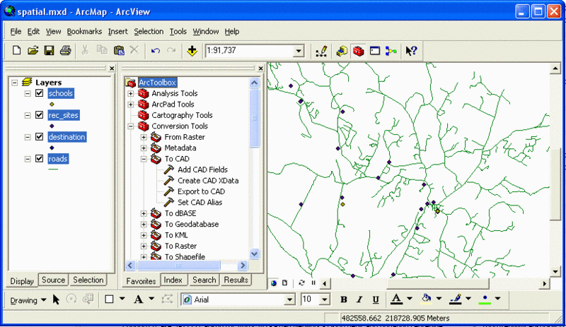
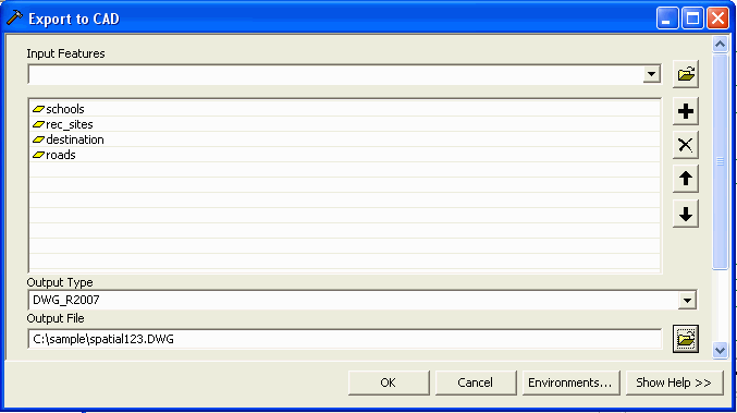
Next, select the features to export in the
Export To CAD dialog. To select a feature, pick the down arrow on
the Input Features first row and pick the feature name from the
list. After selecting the features, choose the output file format
for either DWG or DXF file and the version. For example, choose
DWG_2007. Finally, enter the DWG file name to create and pick
OK.
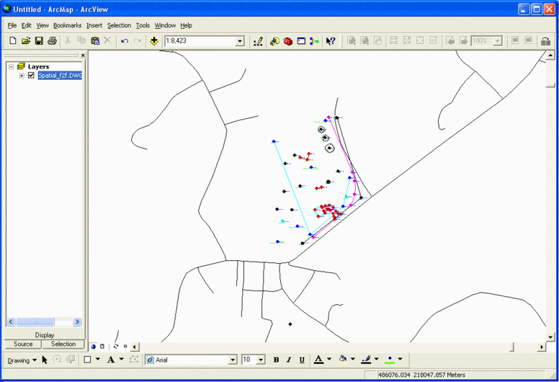
Step 2 (Open Project in Carlson Survey):
Use File->Open in Carlson Survey to open the drawing created by
ESRI.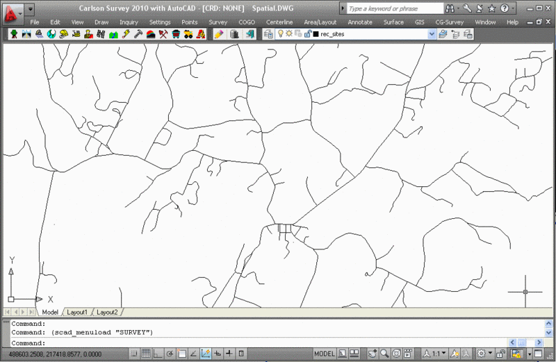
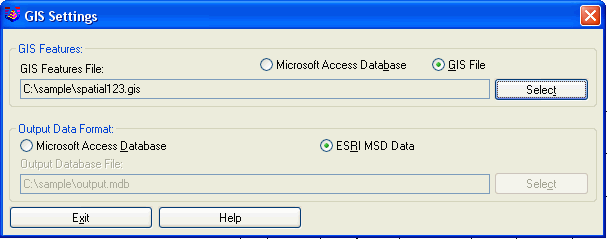
Next, run GIS->GIS Database Settings. The GIS Features File
defines the feature names along with their drawing properties and
attribute names. Choose the GIS File format and set the file name.
For the Output Data Format, choose ESRI MSD.
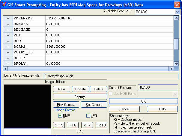
To verify that the GIS attribute data is in the drawing, run
GIS->Input-Edit GIS Data and pick on an entity in the drawing.
The attribute data is shown in a spreadsheet editor. This example
shows the Roads feature data assigned to a polyline.
Step 3 (Export Project to SurvCE):
From the GIS Data menu, choose Export GIS Data to SurvCE. This
command takes selected data from the drawing and creates the GIS
files that SurvCE uses.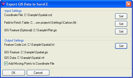
For input files:
Coordinate File: Contains the point database with point#, x, y, z
and description.
Field-to-Finish Table: Defines the coding for the description field
that will be converted into a Feature Code List for SurvCE.
GIS Feature: Defines the feature and attribute names. Using this
file is optional and applies in case that the feature definitions
contain more features or attributes than the data entities.
For Output files:
Feature Code File: This is the SurvCE format file for the
description field coding definitions.
GIS Feature: This defines the feature and attribute names. This
file is automatically named after the Feature Code File.
GIS Data: This file contains the attribute data. This file is
automatically named after the Coordinate File.
Add Missing Points to Coordinate File: This option creates points
in the Coordinate File for any selected point entities that aren't
already in the Coordinate File.
After specifying the files, pick OK and the program prompts for the
entities from the drawing to export. You can select the entire
drawing by entering "all", or select a subset of the drawing
entities. The program will read the GIS data from the selected
entities to create the GIS data file (.vtt) for SurvCE.
Now that the project data is converted to SurvCE format, upload the
coordinate file, feature code list, GIS feature, GIS data and
drawing onto the SurvCE data collector. If you have SurvCE 2.5 or
later, then you can use the DWG file format for the drawing. For
earlier versions, use the DXF format. Depending on your collector
and connections, you can do the upload with either Carlson
Survey->Data Collectors->SurvCE, or Windows ActiveSync, or
transfer on a data card. For this example, we have spatial.crd,
spatial.fcl, spatial.gis, spatial.vtt and spatial.dwg to
upload.
Step 4 (Data Collection in SurvCE):
First download the data files from the SurvCE data collector to the
computer. Get the coordinate file (.crd), GIS data file (.vtt) and
drawing files (.dwg or .dxf).
Step 5 (Download Project from SurvCE):
This step converts the SurvCE GIS data (.vtt) into the ESRI MSD
format for the drawing.
First download the data files from the SurvCE data collector to the
computer. Get the coordinate file (.crd), GIS data file (.vtt) and
drawing files (.dwg or .dxf). Then open the drawing file and use
Points->Set Coordinate File to set the coordinate file from
SurvCE as current.
From the GIS Data menu, choose Import GIS Data from SurvCE. The
routine prompts for the GIS Feature Definition file (.gis) to
process along with the SurvCE data to combine the feature
definitions.
Step 6 (Load Project into ESRI Geodatabase):
Save the drawing file in Carlson and then run ArcView. Pick the Add
Data button in the Standard toolbar and select the
drawing.