Quick Profile
This command allows you to create, view, edit, and report profiles
from the TakeOff surfaces. 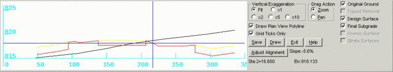 Pick
starting point (CL-Centerline,P-Polyline): To make a profile
you need to define the alignment by: 1) picking points on the
screen; 2) typing in CL in the command prompt, and selecting a
centerline file; or 3) typing in P and choosing a polyline from the
screen. After doing so, the above profile viewer is created.
Pick
starting point (CL-Centerline,P-Polyline): To make a profile
you need to define the alignment by: 1) picking points on the
screen; 2) typing in CL in the command prompt, and selecting a
centerline file; or 3) typing in P and choosing a polyline from the
screen. After doing so, the above profile viewer is created.
The far right dialog box allows you to toggle on and off different
Surfaces to view in the profile viewer including: Original Ground,
Topsoil Removal, Design Surface, Final Subgrade, Overex Surface,
Strata Surfaces. If a surface is not defined in the current TakeOff
project, like Topsoil Removal in this example, than you will not
have the option to display it. In this example, the three Surfaces
that can be displayed, Original Ground, Design Surface, and Final
Subgrade, are displayed in the profile viewer.
When you move the cursor around the profile viewer a crosshair
follows along the surface and reports the Station, Slope %, and
Elevation at each point. It is displayed towards the bottom-right
side of the screen next to Adjust Alignment. In this example the
station is 2+16.650, the Slope is -5.6%, and the Elevation is
818.133. A crosshair can been seen in the profile drawing and along
the alignment in the main drawing as well.
Vertical Exaggeration: x1 is the actual appearance of the
surface(s). Depending on the flatness of the surface(s), you can
select x2, x5, x10 vertical exaggerations to better see the
elevation differentiation and different surfaces. The option Fit
automatically exaggerates the vertical to best fit the profile
viewer.
Drag Action: This dialog allows you to zoom in and out, and
pan around the profile. To zoom in click and drag up, to zoom out
click and drag down. To Pan, click and drag the direction you want
to move.
The Adjust Alignment icon allows to pick the polyline or centerline
that you used and move it to your liking. If you selected an
endpoint vertex, you can pivot that vertex around 360 degrees and
the profiles will update in real time. This is helpful when
checking for spikes. If you select the middle vertex then you can
shift the entire centerline around.
If you created a profile alignment by picking points and you want
to save that polyline you created then toggle on Draw Plan View
Polyline. If you do not choose Draw Plan View Polyline than the
polyline will be lost when you exit out of the Quick Profile
command. Grid Ticks Only marks elevations and distances but does
not draw them into grids.
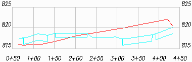
The Save icon allows you to save the profile as a (.pro) file by
whatever name you give it. The Draw icon allows you to draw the
profile right on your drawing. Set the layer name, vertical and
horizontal scale as desired, pick a starting point to draw, and the
profile is created. Note: the below example has a vertical scale of
5 feet per grid and a horizontal scale of 50 feet per grid.
Prompts
Pick starting point
(CL-Centerline,P-Polyline): p
Polyline should have been drawn in direction of increasing
stations.
CL File/<Select polyline that
represents centerline>:
Loading edges...
Loaded 5057 points and 14923 edges
Created 9866 triangles
Prerequisite: a surface
Keyboard Command: TK_QUICKPRO, QUICKPRO