This command develops the linework, geometry and labeling for
subdivision, commercial and industrial sites by using the familiar
Road Network interface and pre-defined settings. The program docks
a dialog on the left of the screen identifying the geometry
settings and all road files and leaves an active CAD screen and
command line. You can save drawings and run virtually any standard
AutoCAD command while within the docked dialog. Once you identify
centerlines for the road network, the program detects intersections
and end segments suitable for cul-de-sacs, and through input of
design parameters for offset criteria, cul-de-sac dimensions and
intersection transitions, the program will process the complete
geometry layout, with output options including creating Lot files
for later reference and a variety of labeling options for such
items as Areas, Distances and Bearings. The road network settings
are saved in a .RDN file.
Before running the Road Network, use the following procedure to
setup the lot labeling settings and site boundary. Click the Lot
Network Settings button. Note that you can use the Area/Layout Menu
pulldown to access these commands as well. Select or create a lot
network settings file. Next, select the Set Boundary icon.
Select a closed polyline for the boundary around your
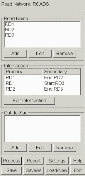
site. Next select the Road Network icon.
When prompted, select the .RDN file from the Existing tab. This is
where the centerlines involved for the subdivision will be defined
and added to the Road Name area of the panel. These centerlines are
standard Carlson .CL files. Click a centerline and choose Edit. If
a CRD file is requested choose or create a .CRD file. The Edit Road
dialog appears. The centerline can be selected here and these
centerlines can be edited on the fly if needed. For ROW Offsets, we
are using the Row-OFF-a.Row file. Click Edit. The ROW offsets
dialog displays. Use the defaults of 45’ left and right and note
that additional graphics can be automatically generated by hitting
Add and entering additional values, names and layers. Hit Exit.
Note also that Optional Input files can be attached to the process
for roadway widenings based on the standard Carlson Road design
tools of the same name. This is where a polyline indicating where
the roadway template ID’s should be tapered or widened is developed
into a Centerline file and attached to the roadway template
involved. Refer to the Road Design documentation for this
information. Hit OK to close the Edit Road dialog. These settings
can be set and altered for each road in the network.
Next click on one of the intersections you may have and select Edit
Intersection. In the Edit Intersection dialog, the intersection’s
radii can be set. Click on the Front Left or Front Right to verify
this. Hit OK when ready.
The program can also develop cul-de-sacs for the subdivision,
although this example doesn’t require one. To see how it works,
click Add under Cul-de-sac’s area of the panel. The Select Road for
Cul-de-sac dialog appears. Select the road for the Cul-de-sac and
the Edit Cul-de-sac dialog opens. Then as shown in the figure,
choose whether the cul-de-sac occurs at the beginning or ending of
the roadway, provide a cul-de-sac radius and filet radius and any
other criteria to develop the graphics as desired. Since we do not
have a cul-de-sac in this example we will skip this step.
Next select Settings at the bottom of the Road Network panel. The
Radius is the default for new intersections. The radius for any
existing intersection can be modified by selecting the intersection
in the list and picking the Edit button. The Create Lots setting
draws linework for lots for the specified geometry parameters.
Otherwise, only the ROW polylines are drawn.
Use a radius of 25.0 and turn on the Create Lots toggle and click
Settings. Set the values as shown in the Create Lot Settings dialog
below. Then hit OK and OK to exit.
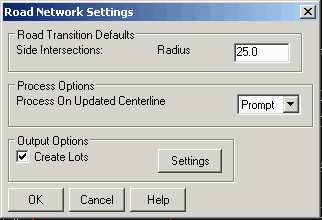
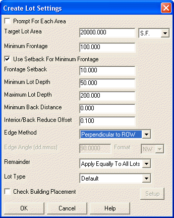
Prompt For Each Area: This option will
pause to prompt for the target area as each lot is created. Target Lot Area: The new
lots will have this area +/- the Lot Area Tolerance under Lot
Network Setting plus any effect from handling the Remainder. Minimum Frontage: Controls
the minimum lot perimeter length along the ROW. Use Setback For Minimum
Frontage: This option bases the Min Frontage check at the
specified Frontage Setback from the ROW. Minimum Lot Depth: This
setting is the min distance from the ROW to the back of the lot for
the lot side lines. Maximum Lot Depth: This
setting is the max distance from the ROW to the back of the lot for
the lot side lines. Minimum Back Distance: This
setting is the min distance along the back of the lot perimeter
between the two lot side lines. Interior/Back Reduce
Offset: For interior boundaries generated by the program
between lots, this option reduces the number boundary vertices. A
vertex is removed if it doesn't affect the boundary by more than
the specified offset amount. This method is similar to the Reduce
Polyline Vertices command. Edge Method: The lot sides
can be created perpendicular to the frontage ROW, back boundary or
at a specific angle. Remainder: This option
determines how to handle any remaining area that is less than the
target area after fitting as many lots as possible. The
Create Separate End Lot
will make a lot with this remainder area. The Apply Equally to All Lots will spread
the extra area to all the lots. The Add To Last Lot will add the remainder
to the last lot created making it larger than the target area. The
Create Back Lot Edge makes
a back lot edge that meets the target area at min frontage. Lot Type: Sets the lot type
for the new lots. Check Building Placement:
Checks that the building footprints fit within the lots for the
specified setbacks.
Lot
Setback Parameters: These setting offset the lot perimeter
inward for different sides of the lot. Min Setback Area: This
option checks that the lot area within the setbacks is at least
this much.
In the Road Network panel click Save or Saveas to save these
settings for your own experimentation.
Now Click Process to begin the lot layout. You will notice the
ROW’s and EOP’s being generated, followed by the lot lines. Then
areas are labeled and setbacks are created. Finally, the lotlines
are labeled with distances, bearings and arc data.
Pulldown Menu Location: Area/Layout Keyboard Command: lotnet_rdn Prerequisite: centerlines and a site boundary
polyline