Surface Equipment Timing
Surface Equipment Timing schedules through surface pits and blocks
based on equipment mining rates in accordance with a calendar. The
mining rate is typically based on volume of overburden but may also
be based on tons of key strata. The calendar is set by the user to
indicate when entire days or individual shifts within a day are
down for holidays, time off, or other reasons. The pits themselves
must contain key strata and overburden information which is placed
in them through use of Surface Reserves, Import Timing Grids, or
Assign Timing Data. Surface Equipment Timing is distinct from
Surface Production Timing by requiring use of quantities or grids
stored in the pits, use of a calendar, and defined rates of
production for equipment. The Calendar, Equipment and Crews are
defined in the Surface Project Manager.
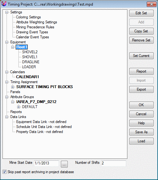
The Project Manager also appears at the start of Equipment
Timing. The purpose of the timing project database file is to
provide a single place where everything related to the timing
project is stored. This includes equipment definitions, reporting
settings, pit and panel information and reports produced. This also
includes other data such as calendars, equipment options, date and
weight tables, text block definitions. Basically everything except
for the grid files, which will be referenced. This means that
reviewing or even repeating results of a schedule done previously
will be much easier if everything including the last results is
stored in the same place.
The left side of the dialog has a tree control
which displays the categories of items on the top level, with
either set of items or actual items underneath. Depending on what
is selected on the left, the buttons on the right will reflect the
functionality available for the current selection. The sets of
items showing in bold reflect the current set when applicable: i.e.
the project can have multiple sets of equipment defined, but the
one showing in bold is one used in calculations. By double-clicking
on the item the Edit function can be executed if applicable. For
equipment, the user can edit, add, copy or remove entire sets of
equipment. Use the Set Current button to set a particular item
current. Equipment can be imported from an older Equipment
Definition file or from another project. It can also be exported to
another file. A number of different data can be output to an
external data source or brought up in the report
formatter.
Following is a detailed description of each function on the Surface
Timing window and subsequent windows. After that is a step by step
procedure for setting up for the Surface Equipment Timing.
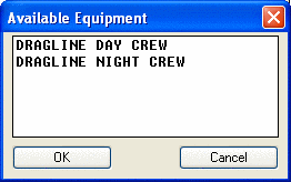
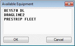
- Add Unit: Selecting
this button will bring up a list of Available Equipment for
selecting a unit to add to the Surface Timing window. This must be
done first, before assigning pits or blocks.
- Edit Unit: This button
will go to the Equipment Production Rate window, similar to Define
Equipment. Any rate or shift changes made here will be saved to the
equipment file.
- Replace Unit: This replaces one unit with
another.
- Remove Unit: This button will remove the highlighted
equipment from the list of Equipment Involved. It will still
remain in the fleet for future use, just not on the list for the
current mine plan.
- Edit
Calendar: This will bring up the active calendar where any
changes and edits can take place.
- Do Earlier: This option will move a selected pit/bench
up the list in the Assignment window.
- Do Later: This option will move a selected pit/bench
down the list in the Assignment window.
- Remove: This option will move the selected pit/bench
from the Assignment window back to the Unassigned
window.
- Remove All: This option will move all of the
pits/benches from the Assignment window back to the Unassigned
window
- Add
Delay: This inserts a delay in-between the pit blocks. This
brings up the same delay setting as found in the Drawing
Events.
- Assign: This button will move the high lighted
pits/benches from the Unassigned window over to the Assignment
window.
- Select: This is to select the pits and their
appropriate benches for assigning. It will highlight them, ready
for the Assign. The choices to select are None, All, or by bench
number, such as all the Bench2, or the Bench3.
- Use
Precedence: This gives the ability to adjust sorting of
unassigned pits/panels so that precedence is satisfied (violating
names are moved down the list until precedence is
satisfied)
- Screen Pick: Selecting this allows for screen picking of
the pits in plan view. Cross-hairs appear, and the command line
states: Pick on or inside of pit polyline or Enter to finish:. Pick
inside the pits in the order they should be assigned. Picking once
assigns the first available bench. Picking again in the same pit,
assigns the next bench (if available) immediately after the first
one. Hit Enter to get back to the Surface Timing screen, and the
pits should be assigned in the order picked on
screen.
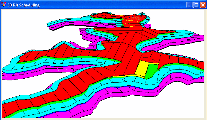
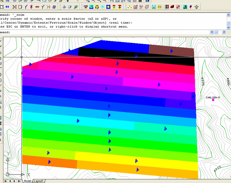
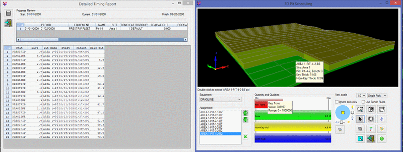
- 3D Pick: This option gives a 3D view of the pits and
the quantities stored in them. It allows for viewing, rotating and
selecting of the pits to be mined in 3D. When a pit and bench is
picked, it disappears from the mine plan, revealing the block
beneath it. There must be a Pit Attribute called SURFACE with the
surface topography grid assigned to it. Rotate the view to see the
benches in 3D, select a unit, and start picking the blocks in the
order to be mined. The “mode” it is in will determine what the
mouse icon is.
- Vertical Scale: This dropdown allows
a different vertical scale set in the window from 1X to 16X
- Single Pick / MultiPick: This
allows for switching between selecting one pit block at a time, or
a range. To select a single pit block, set the mouse to the
arrow/pointer, then double click on a pit block to remove and mine
it. If there is a range of pit blocks to select, choose the Multi
Pick option and using the same arrow pointer, double click on the
starting pit block, and then again on the ending pit block of the
line of blocks to mine. Keep picking until the end of the string is
reached. It will draw a red line from pick to pick. When finished,
Right Click the Mouse, and all the blocks crossed by the red line
will mine out in the order they were crossed. This will remove and
mine that entire range for scheduling.
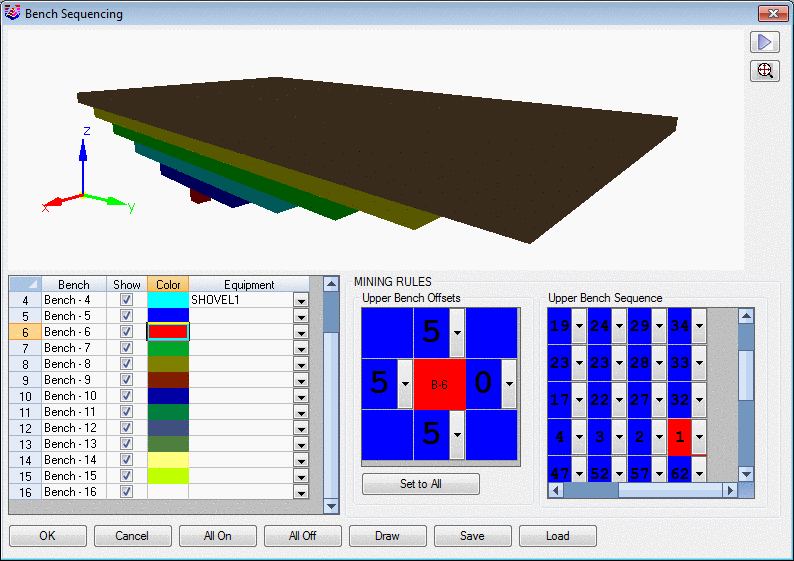
- Use Bench Rules: This option will
apply the bench rules to benches on top and those are assigned to
the equipment selected for each bench in order top to bottom with
defined sequence. The Bench Sequencing screen to set this up is
shown below.
- Zoom button gives the magnifying
glass with the +/- to zoom in and out
- Rotate button gives the XY icon to
tip it on its side, and the Z icon rotates it around the Z
axis
- Pan button gives the hand and pans
around the screen.
- The Pick arrow button is the easiest
icon to select the pits with. Just move the icon on top of a block
and double click with the left mouse button. The name of the pit
and bench it is pointing to is shown above the equipment
window. The block will disappear and the name will be added
to the Assignment list. Any mistakes can be removed with the Remove
Button, the green X.
- The Shade button renders the pit
benches otherwise they are just 3D faces not shaded.
- The Zoom Extents button returns to
plan view, and zoomed to the extents.
- Turn Benches On/Off button brings up
the Set Layers window where unselecting a specific bench will
remove it from the 3D image. Each bench color can be set here for
better 3D visualization. These color settings can be saved and
loaded at a different time. The Mining Rules sets up the precedence
on what must be mined in upper benches to get to the desired block
below. Bench Sequencing allows the user to setup default equipment
for each bench and bench sequencing rules with ability to play back
the sequence with the Play arrow >. A mining sequence rule for
the top bench can be setup for each bench by setting the offset in
North, East, West and South direction where North begins the twist
screen angle from the drawing. Use the Twist Screen command first
to rotate the blocks if they are not laid out on a N-S-E-W pattern.
Once the rule is setup for one bench it could be applied to all the
benches with the Set to All. The Upper Bench Offsets control how
many blocks must be removed in each direction from the bench above.
The Upper Bench Sequence sets the order of how to mine these
blocks.
Once the bench rules are setup, there is an option to select the
Bench to draw the advance on the screen by using “Draw” button,
this will draw the perimeter for each bench on top, to show how
much needs to advance to uncover the underlying bench for the
selected pit. The perimeters will be drawn with the selected color
for each bench in CAD.
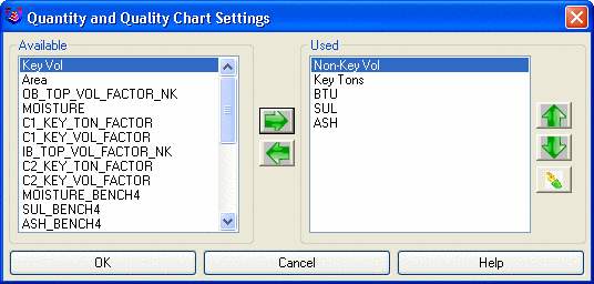
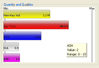
- The Chart Settings button brings up
the window for selecting the bar chart attributes to display.
Everything stored in the pit benches is available to display in the
bar charts. When a pit bench block is selected, the tons, volume or
quality of the bar charts increases to show the values. This shows
a running total of the values as each block is picked and removed
to be mined. The ranges for each attribute set the minimum and
maximum values for the bars on the chart. So, as an example if
200,000 tons are needed for some short range mine planning, set the
Key Tons to 200,000 maximum and then it is easy to see how many
blocks are needed to be picked to get to that volume. Or, if a
certain quality of Key material is needed, select blocks and
monitor the quality to keep it in the desired zone.
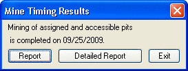
Timing
can be run from this window by selecting the Report button. It
brings up the window with the finish date, where the Report or the
Detailed Report are selected. Choosing Detailed Report brings up
the Report Options and runs the schedule, and hatches the pit
blocks in the drawing.
-
- The blue circle with the yellow
square in it is the light control, to cast shadows where the
light shines from the direction selected.
- The Vertical Scale box changes the
scale for better viewing of sites with low relief.
- Screen Entities button will allow for
any picking in CAD of 3D entities to show up in the 3D Pick window.
Entities such as contours, ramps, roads, pit shells and perimeters
can be selected and viewed with the blocks in the 3D Pick
window.
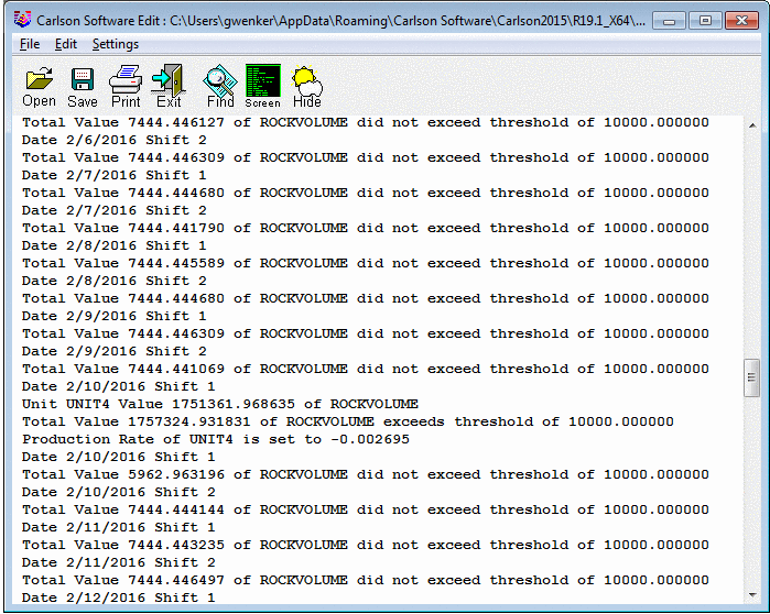
- The Detailed Report button
brings up the window with the
detailed timing report and progress review in a
table.
- When done, just hit the Exit button (the
door with the arrow going out) and you are back to the main Surface
Timing sequencer.
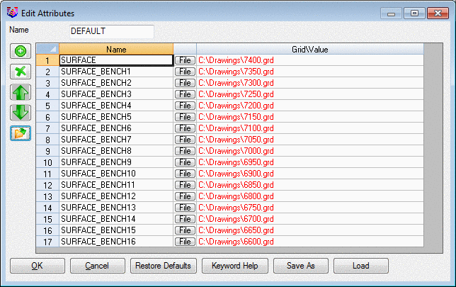
The program uses the SURFACE grid as a starting elevation and the
thickness of each block is relative to the volume of material
assigned to each bench in the pits. Benches with more volume will
show up thicker than others with less. The color scheme is based on
the bench you are on. For better viewing of complex
pits with separate bench polylines in 3D, surface attribute for
each bench can be defined with attribute name SURFACE_BENCH# and
value equal to the bench bottom elevation grid. If these attributes
are defined the program builds the 3d pick view from top-down
calculating the thickness on each pit vertex as elevation
difference between two consecutive benches. The red text indicates
the grids are moved and cannot be found at that path. There is a
reset folder button to address it.
- Add Delay of Days/Shifts:
Adding a number in the day or
shift window and hitting the Add Delay button will bring up the
following windows. Highlight the pit/bench in the Assignment window
and the delay will be added below the row that is
highlighted.
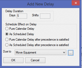
The Schedule Effect on Delay gives four choices:
- Pure Calendar delay, where if the calendar has it off already,
then that is all it will do. It will not take it off
additionally.
- As Scheduled delay, where the delay will take affect when the
equipment is working. If the calendar has the equipment off at that
time, then the program waits until it starts to work again, then
schedules the delay.
- Pure Calendar Delay after precedence is satisfied.
- As Scheduled Delay after precedence is satisfied.
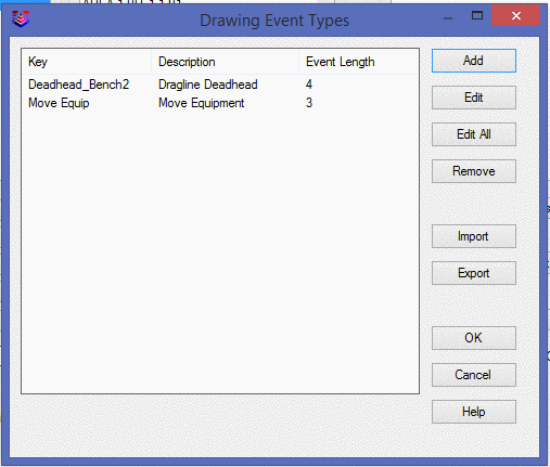
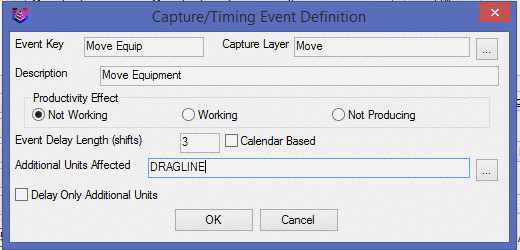
The Due To option provides Drawing Event Types to choose from.
Choose the button with "..." next to the Due To, to open the
Drawing Event Types window. To Add or Edit a type, the
Capture/Timing Event Definition screen provides names and
productivity options. Anywhere the text drawn in the Capture Layer
is encountered in the drawing, the equipment will be delayed by the
Event Delay Length in shifts. The Productivity Effect is the result
of the delay. Not working is where the equipment is completely
down. Working is no change, and Not Producing is where the
equipment is in use, but no quantities are being mined. There is
also an option to apply a delay only for additional units which are
specified above.
- Assigning Bench Specific Events:
If you want an
event to associate with a specific bench put the event on the layer
with “_BENCH##” (## - Bench Number) suffix to layer name. For
example if the dragline move event occurs only on the bench 3 the
capture layer name would be “DraglineMove_BENCH3”, if there isn't
any _BENCH## it would apply to all the benches. Also update the
Capture Layer name in the event definitions to
“DraglineMove_Bench3”.This would make sure that drawing event will
occur only on the equipments working on Bench3. You can specify
other event on specific benches same way.
- Undo Report: This option will Undo a previous Surface
Timing run. It will delete the blocks or perimeters drawn in the
drawing. If a quick change to the plan or equipment is made, it can
be re-run very quickly just by hitting Undo Report and then
Calculate again.
- Starting Date: This must be filled in before selecting
Calculate. Use the format that is defined for dates in Configure
under Settings. It can be 12/15/2014 (month/day/year) or 15/12/2014
(day/month/year) etc.
- Number of Shifts: This is the number of shifts the program
will use in the actual sequencing. Even if 3 shifts are defined for
the equipment or in the calendar, and 2 is entered here; it will
only use 2 shifts in the timing. It uses the first two, ignoring
the third shift in the equipment rate and calendar.
- Skip Ore (Key Strata) for Timing:
This toggle will determine if
the equipment is mining just the NonKey/Overburden material or both
the NonKey and Key Material that appears in the pit and bench. For
example, a dragline moving overburden should have this checked so
that it ignores the coal volume. It will still report the Key
volume and tons, but not use it for the schedule.
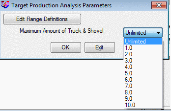
- Perform Bottleneck Analysis /
Bottleneck Parameters: Bottleneck analysis is an option in Surface
Equipment Timing that lets you limit the total production from
several units to a specific level, even if the sum of the units’
production exceeds the set level. To use this method, check the box
for Perform Bottleneck Analysis and then set the
parameters.
-
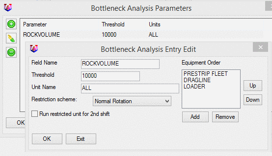
The Bottleneck
Parameters dialog box is found on the Surface Timing dialog under
the Bottleneck Params button. The Field Name you specify must
match one of the reserved words for volume, tons, or a user-defined
attribute. These reserved names can be found in the Edit User
Attributes section in the final report if they are not known. The
Threshold value is another name for the limit placed on the
attribute name. This limitation can be set for specific
equipment units, and it can be set for ALL units as well. To
set the unit preference order, ADD them to the dialog box to the
right under the Equipment Order heading. The order can be
changed by highlighting the unit (by selecting it with the left
mouse button) and picking the UP or DOWN button to the right.
There are several
schemes you can use to determine which units are restricted to meet
to required level.

When production capacity exceeds
the systems ability to absorb it some units need to be scaled
back. The options available to reduce production
include:
1.
Normal Rotation - alternates in
order through the units.
2.
Hold Lead, rotate rest – operates
the primary unit at full capacity and alternates through the rest
of the units reducing production.
3.
Hold tail, rotate rest -
opposite of Hold Lead.
4.
Fixed order – maintains the order
of unit preference reducing production, beginning with the tail
unit until it is completely down, then reducing the next in
preference order until the objective is met.
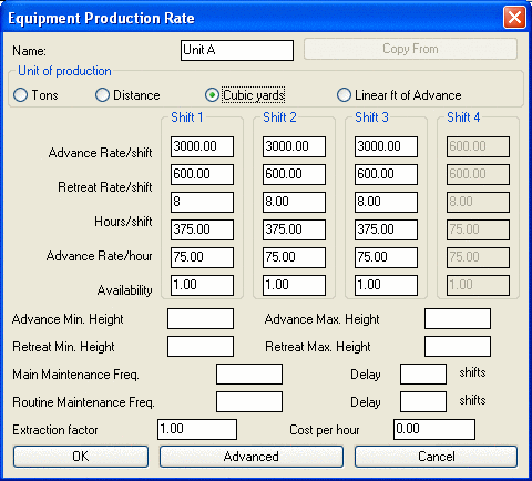
Example: There are 4
excavators on a job (Units A-D )with a capacity of 3,000 cyds per
shift. All of the material must be loaded in trucks and
hauled away. There are 6 trucks in the fleet with the ability
of hauling 1,000 cyds per shift. Therefore, the trucks in
this case are the bottleneck of 6,000 cy/shift, limiting production
of the excavators.
-
Using the
fixed order as the restriction scheme, we will limit the tail
unit’s production every shift that the excess excavator capacity
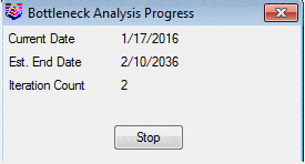
exists. When the schedule is run, it checks the shift
capacity for each shift as the program times out the
progress. This slows the program down, showing a bottleneck
window with the dates counting by, but keeps the production
capacity in line with the desired production level. A report
is generated showing which unit is reduced and by how much. An
example report is shown here.
-
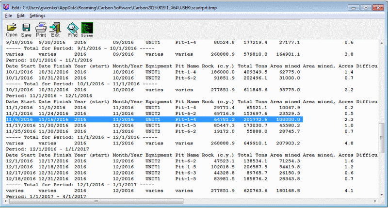
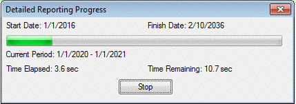
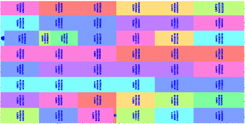
When the schedule is
run and the map is hatched showing the progress, note the
additional time periods for Units 3 and 4. This shows Units 3
& 4 have been held back while the other units worked at full
production. Unit 4 is not even working in some of the early months.
There is a progress bar to show the time elapsed and time remaining
for very large mineplans that take a while to run.
A report shows the amount added
by unit.
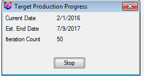
- Calculate: This is the button to start the sequencing.
Choosing this button will bring up a small window displaying the
completion date. Or if the bottleneck parameters are being used, it
will display the days counting down and the various Loops it is
using in the calculations. There are two report choices shown here.
The Report button will bring up the Equipment Report where the
following parameters, such as start and finish dates and the days
waiting or pit available are displayed. This is useful to determine
if there is a delay due to a unit holding something up. The
Detailed Report will go into the Report Options Screen described
next. This is the same as the Report button from the initial
screen.
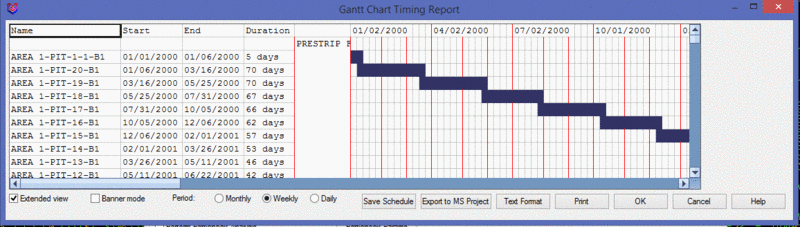
- Gantt Chart: Selecting this will go into the Gantt Chart
Timing Report window. It should only be active if the Calculate
button has be selected previously.
This report can be saved as
Excel file or can be exported to MS Project (csv) file for the
further analysis.
- Report: Selecting this will go into the Report
Options screen. It should only be active if the Calculate button
has be selected previously. This is where many settings in the
schedule are set, such as the breakdown of the time periods,
hatching etc. The Report Options is defined next.
Report Options. Each item on the dialog box is defined
below.
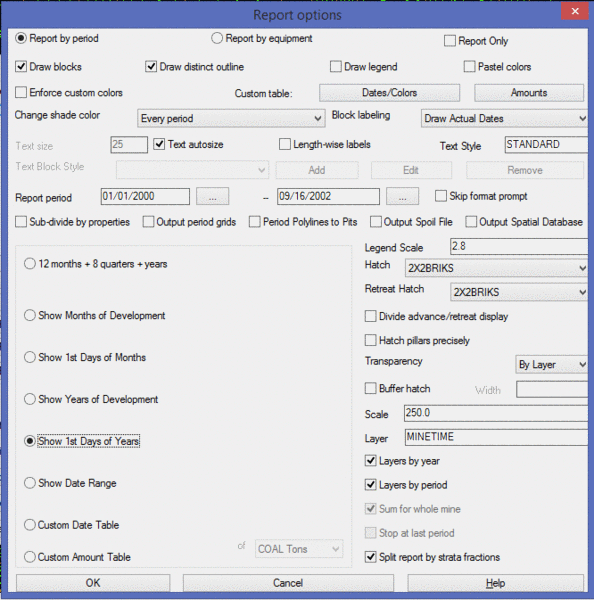
- Report by period: This
option runs the schedule and breaks the pits into blocks by period,
such as month or year. The blocks and outlines are colored by
period and displayed in the report. The report can be formatted may
ways.
- Report by equipment:
This option runs the schedule and breaks the pits into blocks by
Equipment. The blocks and outlines are colored by equipment and
displayed in the report. The report can be formatted may
ways.
- Report Only: Choosing
this option will not draw any blocks or outlines on the map. It
will go directly to the Report Formatter for viewing of the
data.
- Draw blocks: When this
option is selected, the periods or equipment will be drawn as
blocks of solid fill or any AutoCAD hatch pattern that is
chosen.
- Draw distinct outline:
When this option is selected, the periods or equipment will be
drawn as closed polyline outlines.
- Draw legend: This
option draws a legend and the picked location on the map. The
colors are based on period, custom amounts or equipment.
- Pastel colors: Choosing
this option draws the blocks or outlines in the pastel color region
of the AutoCAD palette. It uses colors in the 11, 21, 31, 41 etc.
row. If it is not selected, then it will use the brighter, primary
colors such as 10, 20, 30, 40, etc. This is useful for plotting,
the colors are lighter and use less ink.
- Enforce custom colors:
Selecting this option will use the custom color palette the is
setup with the Custom Dates and Colors Table.
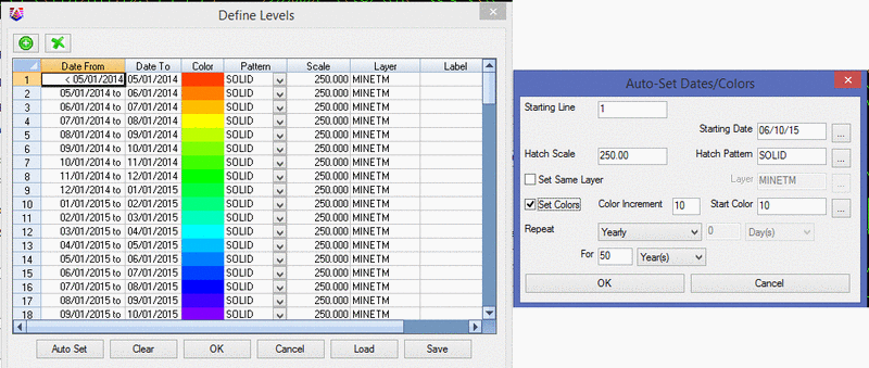
- Custom table:
Dates/Colors: This brings up the Define Ranges screen. This
is where a custom date or color table can be set up. The Auto set
button will bring up the smaller window for entering the starting
line (row number), starting date, how often to repeat, and how long
to keep repeating. The Set colors will prompt for a starting color,
and the color number increment. The colors are set by picking the
color box. The Pattern is the pattern of the hatch in the blocks.
The Scale is the size of the hatch patterns if a hatch is used. The
Layer is the AutoCAD Layer of the period. Finally, the Label is
what each period will be called for reporting and labeling.
The example shown here has created a weekly schedule with custom
colors. The Clear button wipes out the data for starting over. The
tables can be saved and loaded as CDT files. To use this option,
choose Enforce Custom Colors or Custom Date Table.
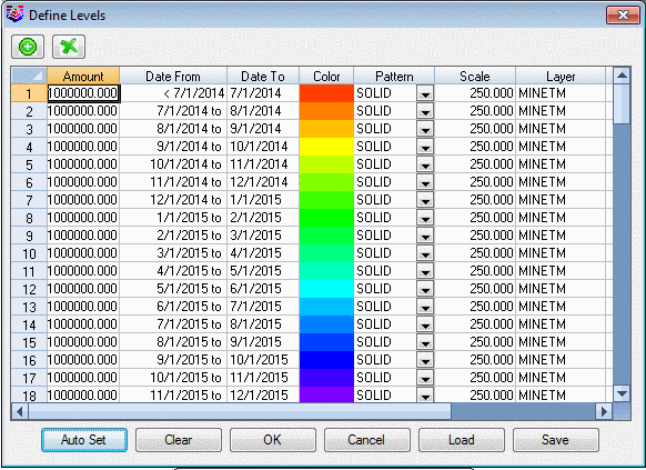
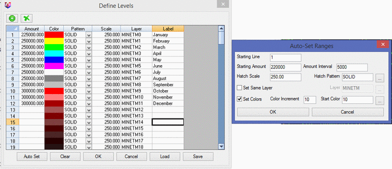
- Custom table: Amounts:
This button brings up the Define Levels window. This is where the
amount to target is set for the Custom Amounts option in the
report. The amount to target is set in the first column. The next
column is the color for the blocks and outlines. The colors are set
by picking the color box. The Pattern is the pattern of the hatch
in the blocks. The Scale is the size of the hatch patterns if a
hatch is used. The Layer is the AutoCAD Layer of the period.
Finally, the Label is what each period will be called for reporting
and labeling.
- Change shade color
every: This option will change the color/layer of each block
or outline. There are 3 choices. Every Period (what is selected
below), Year, or 5 Years.
- Block labeling: This
pull-down is for setting the labeling options. There are 5 options
here. No Block Labels will not draw any labels. Draw Actual Dates
will draw the date of each period. Draw Period Names will place the
period name in the block that is entered in the custom date table.
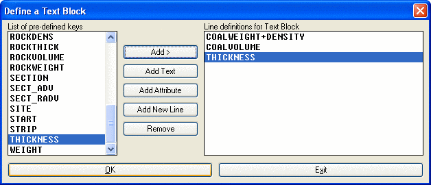
Use Custom Names draws the names entered in the custom amount
table. Use Custom Text Block activates the Add, Edit and Remove
buttons. Choosing Add or Edit will bring up the input screen for
arranging the text items in the block. First, give the new block a
name. Then move items from the left side to the right, in the row
desired. The Add Text button allows for custom text for prefix or
suffix entry. The Add Attribute adds any attributes that exist in
the schedule. Add New Line moves the added item to the next row. If
this is not selected, then the next item is added to the same row,
with a + as a separator. Remove will move the entire row from the
Line definitions.
- Text Size/Text
autosize: This will either place all text in the map with
the defined size, or autosize it to fit in the block
dimension.
- Length-wise
labels: This option draws the text parallel with the
long axis of the pits. If it is not selected, then the text will be
90 from the long axis.
- Text Style: Enter in an
AutoCAD text style for labels.
- Text Block Style: This
section is active if the Block labeling is set to Use Custom Text
Block. Any premade blocks will appear on the list and may be
selected for text orientation.
- Report Period: This is
the start and finish date of the report. By default, the program
will display the full range from the start date to the final date
it needs to finish. Any date range in the middle may be
used.
- Skip format prompt: If
this option is selected, then after the blocks are drawn, a report
will appear that is similar to the last one created. The program
will not bring up the report formatter for customizing.
- Sub-divide by
properties: If this is selected, the schedule will recognize
any named Carlson property lines drawn on the mineplan. In the
report, the periods can be further subdivided by property and
owner. These are the same property lines that are used in Surface
Mine Reserves.
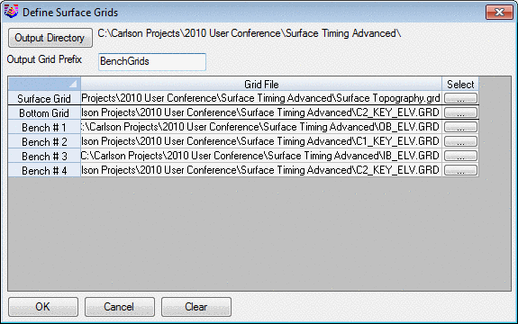
- Output period grids:
Choosing this option will create a grid file of the 3D surface at
the end of each period, such as a month or a year. It needs the
Surface Grid and the Bottom of Pit Grid. It needs at least the
Bench 1 Grid filled in to make the grids. The Bench Grids will come
in automatically from the Pit Attributes, where the SURFACE
attribute is defined as the topography, and each benches bottom
elevation is defined as SURFACE_BENCH*. If they aren't define in
the Pit Attributes as such, then each grid will need to be selected
here. A new output grid path with an Output Grid Prefix is set to
create new grids of each period. A new grid file is then written of
each period for the pit and bench. This can be an "ultimate pit"
used in other design work. It doesn't have the flexibility of other
commands such as Design Bench Pit, but it gives a 3D surface of
each period mined. It uses a constant highwall slope of around 80
degrees, but varies based on the grid cell size.
- Period Polylines to
Pits: Selecting this option creates and names the outlines
as Carlson pits. The names of the pits are the actual period names.
This is useful if these period polylines need to be saved and
re-run in the Surface Mine Reserves for additional quantities or
analysis.
- Output Spoil File: This
option creates the SPO file that is used for the timing of the
spoil commands found in the Spoil menu. This output contains the
nonkey waste for spoil placement and timing.
- Output Spatial Database: This option creates the SQLITE
file with a spatial database.
- 12 months + 8 quarters +
years: A schedule run with this option will break down the
first year into 12 monthly periods, the next two years into 8, 3
month quarters, and the remaining periods will be full
years.
- Show Months of
Development: This method will use the starting day and
increment by month to the same day. For example, if the starting
day is on the 12th of each month, the schedule will be from the
12th to the 12th for each month.
- Show 1st Days of
Months: This method will use the starting day and increment
to the first of each month. For example, if the starting day is on
the 12th of the first month, it will go to the end of the first
month and then start fresh on the 1st of each month.
- Show Years of Development:
This method will use the
starting day and increment by year to the same day. For example, if
the starting day is on June 15th, the schedule will be from June
15th to the next June 15th.
- Show 1st Days of Years: This method will use the starting day and
increment to the first of each year. For example, if the starting
day is on June 15th, it will go to the end of the first year and
then start fresh on the 1st of each year.
- Show Date Range: This option is used to just display a period
as a partial range. Enter a range above in the Report period
windows. Then when the sequence is run, only that period will be
hatched all in the same color and time.
- Custom Date Table: When a custom Date/Colors table is defined,
this option must be selected to use it. Custom Dates/Colors are
defined above.
- Custom Amount Table: When a custom Amount table is defined, this
option must be selected to use it. Custom Amounts are defined
above.
- Legend Scale: If the Draw Legend box is selected, this is
the size of the legend. Sizes from 50-100 should appear legible for
most mineplans with a dwg scale of 50.
- Hatch: This is the hatch that is used for drawing
in the blocks if the custom date or amount tables are not used. All
hatch patterns appear on the list, the most common one, solid,
appears at the top of the list for easy selection.
- Retreat Hatch: This is used for underground retreat
hatching. Disregard for surface mining.
- Divide advance/retreat display:
This is used for underground
retreat hatching. Disregard for surface mining.
- Hatch pillars precisely: This option
allows to leave pillars unhatched. The hatch applies only for mined
area.
- Buffer hatch: This will create a
boundary of each period with the specified border width.
- Transparency: This setting controls
the level of the hatch transparency.
- Scale: If a hatch pattern other than Solid is used,
this is the scale it will be drawn at. Sometimes trial and error is
needed to get the best scale, as different patterns look better at
different scales.
- Layer: This is the AutoCAD layer that the blocks
and outlines will be drawn in, if no other options are
used.
- Layer by year: The blocks and outlines will be layered by
year. The year will appear as a suffix to the layer
name.
- Layer by period: This option will put each period on its own
layer. If there are many periods, it will create many layers which
can be a hassle.
- Of, Sum for whole mine &
Stop at last period: These options are only active when
using the Custom Amount Table. The "Of" window is for selecting
what is being target for custom amounts. The options are similar to
Surface Production Timing: Total Tons, Key Tons, Waste Tons, Total
Area, Mined Area, Total Volume, Waste Volume, and User Grid. Sum
for whole mine will keep a running total for summation in the
report. Stop at Last Period will end the schedule at the last
entered row in the Custom Amount Table entered above.
- Split Report by Strata
Fractions: This option will utilize the tonnage and volume
factors stored as pit attributes and report out the volume and tons
of each named seam, not just composite Key Tons and Nonkey
volume.
Multi-Bench Mining Example Setup:
The defining of equipment, crews and equipment calendar are
(potentially) one-time operations. Similarly, the making of the
"Pre-Calc Grids" geologic model need be done only once in advance
of numerous timing runs. Surface Equipment Timing, also distinct
from Surface Production Timing, allows multi-bench mining by use of
different equipment or the same equipment mining different benches,
with different production rates. Since single-bench mining is a
subset of multi-bench mining, this will illustrate the command with
a multi-bench example. Surface Mine Reserves is one of three
methods to place quantity and quality information into the pits, by
bench. This example will use Surface Mine Reserves. If there are
two benches, Surface Mine Reserves must be run twice, one
time for each bench. The dialog within Surface Mine Reserves should
be completed as follows for Bench 1:
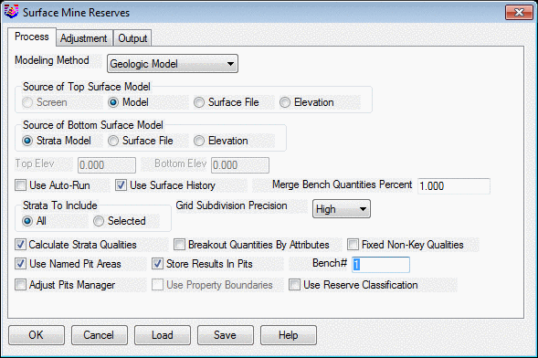
The key is to choose "Selected" strata (for benching) as well as
"Use Named Pit Areas" and "Store Results in Pits". You should also
select "Calculate Strata Qualities" to assign quality information
to the pits. If single-bench mining is conducted, you may omit the
"Selected" option. Other items in the dialog are set according to
user preference. Note the option "Output Thickness Grids". If this
is not selected, total quantity and composited quality information
is placed in the pits, and mining across a single pit is
proportional. However, if the "Make Thickness Grids" option is
selected, mining across the pits picks up the varying of the
overburden thickness, coal thickness and quality information. For
small pits or "blocks" as they are sometimes called, storage of
total information will still lead to reliable results. Thickness
grids are recommended for large and long pits, where the thickness
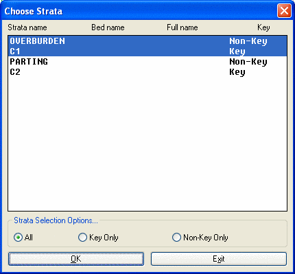
will vary. The choice of "Selected" strata requires that the user
select which strata will be mined in Bench 1. The following Choose
Strata dialog at will appear:
Holding the CTRL or SHIFT key down, will select Overburden and C1
to mine down to the bottom of the first coal (C1). Bench 2 would be
comprised of Parting and C2. Following two runs of Surface Mine
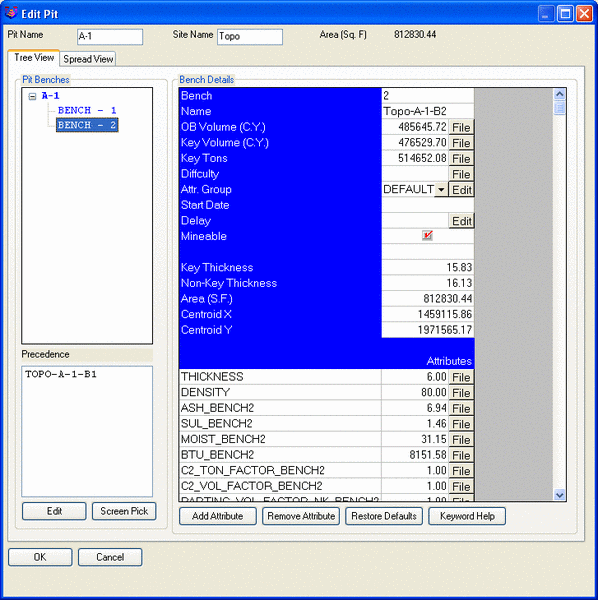
Reserves, new information has been added to the pits. Pits contain
up to three categories of information: pit name (verified by using
"Identify Pit Polylines"), pit direction and pit
quantities/qualities organized by bench. Pit quantities and
qualities are needed only for Surface Equipment Timing, and can be
verified using the command "Edit Pit". For example, the information
in Edit Pit is shown below. Select the "Attribute" option to reveal
the quality attributes.
You will note that Bench 2 has Bench 1 (referred to as TOPO-A-1-B1)
as a "precedence" bench. In other words, you cannot mine Bench 2
unless you first mine Bench 1. Lower benches are automatically set
to require prior mining of upper benches (The ordering of the
mining comes later!). The Pit Attributes show any attributes set by
Define Pit Attributes. Some may be seen here.
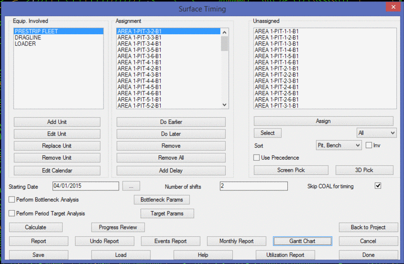
Assuming that a calendar has been established (multiple calendars
can be saved and recalled), and assuming that equipment has been
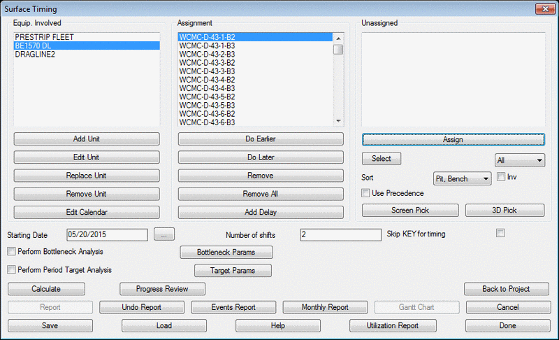
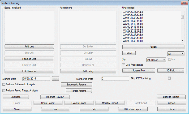
defined, we are now ready for Surface Equipment Timing. After
selecting OK on the Mining Project screen, this is how the dialog
appears prior to making any selections.
Select the equipment and add them one at a time. The equipmet used
here are defined based on two, 12 hour shifts. The "Availability"
option can be used to de-rate the mining speed in the Edit
Equipment. Any of the above items can be revised from within
Surface Equipment Timing. The next step is to assign "Prestrip
Fleet" to Bench 1. It is best to Sort by "Bench, Pit" and then
Select "Bench 1", using the options at middle right in the Surface
Timing Dialog. These leads to the following appearance:
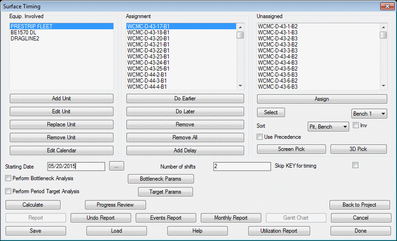
It is also important to note the option "Skip Coal for timing" at
the lower right of the dialog box. Here you can base all progress
on the NonKey overburden and parting only, on the assumption that
the loaders or other equipment digging the coal will "keep pace"
with the equipment removing the overburden and interburden. If
"Skip Coal for timing" is not selected, the coal volume will be
included in the total quantity mined by the equipment. We can add a
second piece of equipment, then highlight it within the Surface
Timing dialog and assign all the remaining pits and benches to it
(Select All or by bench number, then Assign). Note also that we can
add a delay between completing the Bench 1 pit and beginning the
Bench 2 pit. Delays are automatically inserted below the
highlighted pit, so if a pit is highlighted, a delay will be added
below it that can be moved up or down also. There is a prompt to
add this as a calendar or schedule delay (described above).
Shown below is the assignment for the additional benches.
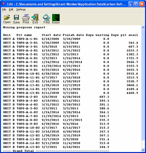
To complete the calculation, fill in the Starting Date (if the
default is not correct), then click on Calculate. This leads to a
completion date and the option of a unit report or going directly
to the Report Options screen. The Unit Report is very instructive
because it highlights when equipment has been idled. Our Bench2
equipment is waiting each time for the "slower" Bench1 unit to
complete bench 1 before it can launch into bench 2. The planner
could try lower rated equipment, or reverse the assignments of the
equipment, or simply re-shuffle the assignments in any desired
manner to maximize efficiency. The last step is to choose "Report"
when returned to the Surface Timing dialog which brings up the
Report Options dialog.
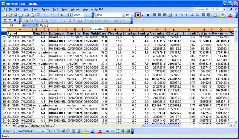
This example will show the first days of months. This leads
to the final hatching shown below as bench 1(the bench 2 layers
were frozen for better appearance), as well as the quantity report
which can be formatted many different ways and exported to Excel or
Access:
Notes and Comments on Equipment Timing:
Equipment Timing can mimic Surface Production Timing through
selection of "Custom Amount Table" at the base of the Report
Options dialog. This would be an alternative way of getting to
custom table amounts, since the equipment is removed from the
equation and is therefore irrelevant. This will target tons of
coal, yet report out how many dragline hours need to be scheduled
to uncover the coal.
If there are multiple seams (both Key and NonKey) assigned to one
bench, the program will report a tonnage and volume factor that
applies to each strata. This factor can be used in the User
Attributes to calculate the tonnage and volume of each separate
strata instead of just a composite number of Key and NonKey.
While Surface Production Timing reports total quantities broken
out by seams or specific strata, Surface Equipment Timing only
reports totals for all key strata (eg. coal) and overburden, unless
Split Report by Strata Fractions is turned on. However, Surface
Production Timing does report specific quantities (composited) for
each bench. Therefore, a 2-bench mining example will report
quantities for Bench 1 (coal C1) and Bench 2 (coal C2). With
sufficient benching, the individual strata quantities are retained.
For one-bench mining, all multiple strata are composited in the
final report.
To practice "what-if" scenarios, use "Undo Report" within the
Surface Timing dialog, which will remove the colored hatching,
allowing revision of equipment assignments and another practice
run.
Prompts
Select all pit polylines.
Select objects: Pick all polylines
Pull-Down Menu Location: Surface Mining menu, under
Surface
Keyboard Command: timepit
Related Commands: Surface Mine Reserves, Assign Directions,
Surface Project Manager, Assign Timing Grids, Import Timing Data,
Define Pit Attributes