This tutorial shows how to design steps of Cast Blast Profile,
Dozer Push and Cut & Place in cross section for dragline
extended bench and spoil side methods. It then takes this design
"template" and applies it to plan view in 3D, extruding it up and
down the pit using a centerline file (CL). Other routines we will
use include Define Dragline Equipment, Cut Only (coal removal),
Draw Dragline limits and Flatten Spoil Top.
Creating Surface
and Strata Cross-Sections
The first step is to generate a cross section of the ground surface
and desired strata. This can be accomplished with the fence diagram
routine, or drawing multiple profiles or sections that represent
these surfaces on a grid. If the fence diagram method is used, be
sure and turn off hatch fence diagram, and turn on draw strata
polylines as single polylines. Otherwise, the strata will be closed
polylines and the program won’t use them correctly. If the profile
crosses an existing, open pit and seams are cropping, be sure to
turn on Draw Surface Polyline in Fence Diagram. This will draw a
continuous polyline across the entire length of the section, needed
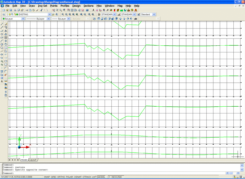
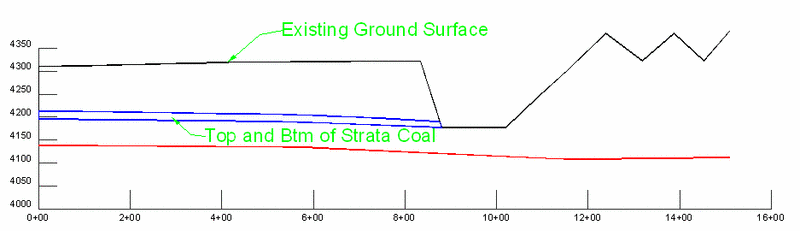
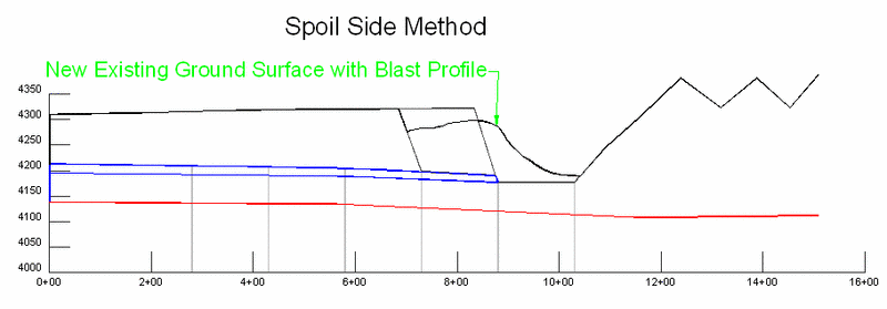
for Cut & Place. Shown is a cross-section of an existing pit.
In all diagrams, the existing ground polyline will be represented
by the thicker, black line.
Cast
Blast
The first operation is to simulate the cast blast for creating the
extended bench. The generic profile of the blast can be defined as
either a Carlson profile (*.pro) or as a polyline drawn on the
screen, above the fence diagram. The profile file or polyline must
be created before running Cast Blast. For example, you can draw the
typical blast profile on the cross-section view. The program will
move the polyline up or down to balance the cut and fill areas.
First, the program has a dialog box for options.
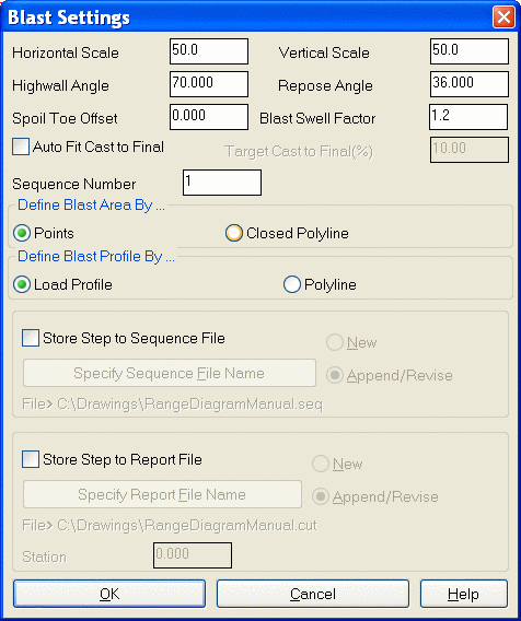
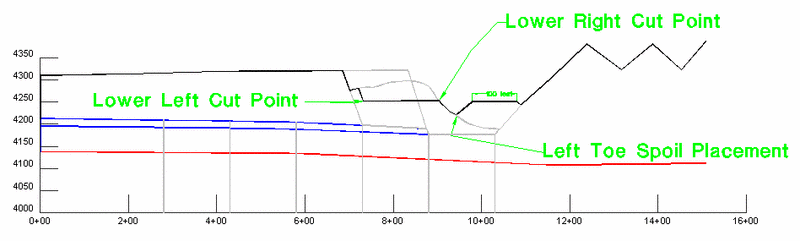
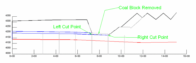
In this case, the swell factor was set to 1.2, or 20% and the
profile by polyline option was used. Then select the ground and
top-of-strata polylines. Next pick the blast or cut area, this
example used the lower left and lower right cut points. The left
point in this case should be at the cut width, and the right point
is snapped to the intersection of the top of coal outcropping at
the existing ground surface.
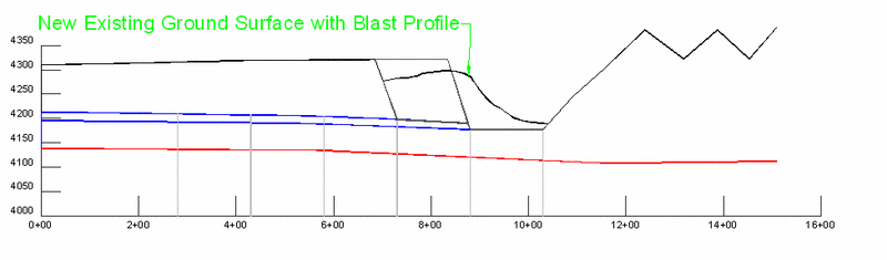 After
the program places the blast, it prompts the user if there is any
vertex on the blast that needs to be moved or changed. Simply pick
the position and the line will move to that location. The existing
ground surface line has now been changed, and is ready for the next
step.
After
the program places the blast, it prompts the user if there is any
vertex on the blast that needs to be moved or changed. Simply pick
the position and the line will move to that location. The existing
ground surface line has now been changed, and is ready for the next
step.
Dozer
Push
Now the Dozer Push command is used to create the extended
bench.
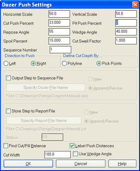
In the dialog box, set the Pit Push Percent to 0%. This will push the material horizontally out into the pit. Turn off Label Push Distances, otherwise it will label the complete surface line. Also set the swell to 1.0 since this material has already had the swell factor applied from the Cast Blast. Choose OK and pick the left and right cut points as shown below. Use the Nearest Snap to pick the right cut point so it connects directly on the existing surface line. The left and right cut points should be selected at the same elevation if the push is to be flat before the pit also. The existing surface polyline has now been updated and is ready for the next operation.

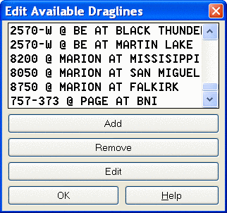
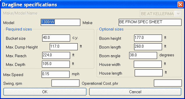
Define Dragline
Equipment
This routine simply defines the dragline parameters and dimensions
for drawing its reach, depth and height on the range diagram. Fill
in at least the required size parameters on the left side of the
box. Many Companies supplied their dragline parameters and are on
the list for easy reference.
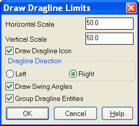
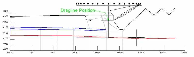
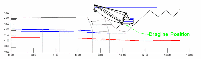
Draw Dragline
Limits
This draws the workable limits of the dragline on the range diagram
cross-section. Pick the existing ground polyline and the location
that the center of the machine is sitting. A block of three lines
is drawn representing the height, digging depth and horizontal
reach of the dragline. There is a vertex placed at the intersection
of the ground surface, this is the point to pick for moving the
block to the next cut. The vertical line above the vertex is the
height, and the line below the vertex is the digging depth. These
are the limits to stay within when cutting and placing spoil. There
is an option to draw a dragline icon, and also to label the swing
angles across the top. This allows you to keep the spoil placement
within a certain swing angle. There is a prompt to use a reference
point. This could be the crest of the highwall. If one is picked,
then it prompts for a distance from that reference point to the
center pin of the dragline. Negative values will offset it to the
left.
Cut
and Place
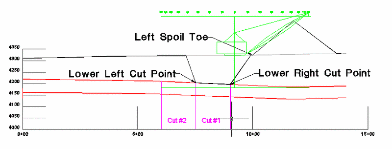
The next step is the Cut & Place command for the dragline work.
In the dialog, set the right highwall angle to the repose angle of
the spoil. This will ensure the cut and spoil are the same angle.
Also set the spoil placement method to Left Toe.
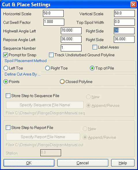
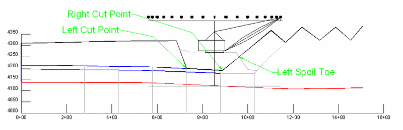
After selecting OK, pick the ground and strata (top) polylines. Next, pick the left cut, right cut and spoil location points as shown. It is very helpful to use the Osnap endpoint and intersection to get the exact points. Notice how the right highwall angle and the spoil match for an accurate representation of the slope. Again, there is no need to swell the material as it has been already swollen from previous operations.
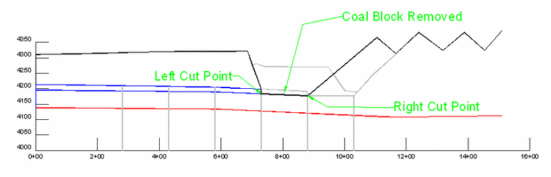
Cut
Only (Coal Removal)
The final step in this example sequence is the removal of the coal
to prepare the new existing ground surface for the next cut/spoil
placement. Like Cut and Place, this routine also allows for
differing left and right cut slopes. The strata polyline in this
case will be the bottom of coal polyline, which will bring the
existing ground polyline down to it.
Cast
Blast
The initial cast blast is the same as the extended bench example in
the previous pages. Shown is the cross-section after the cast.
Spoil Side
Bench
The Cut & Place routine will be used to create the spoil side
bench in this example. In the dialog box, set the Top Spoil Width
to the bench width (in this case, 100 feet). Then choose OK and
select the ground polyline and cut points as shown. Again, the snap
nearest is useful for selecting the right cut point. Do not select
a strata polyline, as we are not going down that deep in the cut.
To place the spoil, be sure to select either left or right toe for
location method, as there is no spoil peak with which to place it.
After placing the spoil pile, there is an option to adjust the left
and right cut points. Any adjustment of the cut area is
automatically reflected in the spoil bench, which allows you to
adjust the spoil bench height.

Draw Dragline
Limits
The next step is to show the dragline limits when placed on the
spoil side bench. Use the same procedure as in the extended bench
example. Another option is to create a block drawing of a dragline
and insert it into the drawing to represent the correct dimensions.
Shown below is a block of a dragline to scale, inserted into the
above range diagram.
Cut
& Place
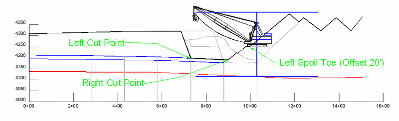
The next step is the Cut & Place routine for the dragline pass.
In the dialog, set the right highwall angle to the repose angle and
set the spoil placement method to Left Toe. Also set the Top Spoil
Width back to zero. Then click OK and select the ground and strata
polylines. Next, pick the left cut, right cut and spoil pile points
as shown. Notice the right cut point is to the right of the coal
block to ensure it is uncovered and minimize rehandling. You can
use the Osnap-endpoints to get the exact points. To start the spoil
pile 20 feet from the spoil side bench, use the distance option and
pick the edge of the spoil side bench as the reference. Type in a
positive value to offset to the right and negative to offset to the
left.
Cut
Only (Coal Removal)
As in the previous example, the coal removal is the last step to
prepare the existing ground surface for the next cut. The right
side cut angle is again set to the same angle as the spoil repose
to simulate the spoil down to the bottom of the removed coal
block.
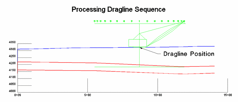
Process Dragline
Sequence
One thing not mentioned in the previous examples is the saving of
each step to a dragline sequence file. The option to store each
step in a sequence file is set at the bottom of the dialog boxes.
Typically the first step is saved to a New file as sequence step
#1, and each subsequent step is appended to that file as #2 and up.
The next example will show a simplified two-cut Cut and Place on a
fence diagram and then processed with a centerline to generate 3D
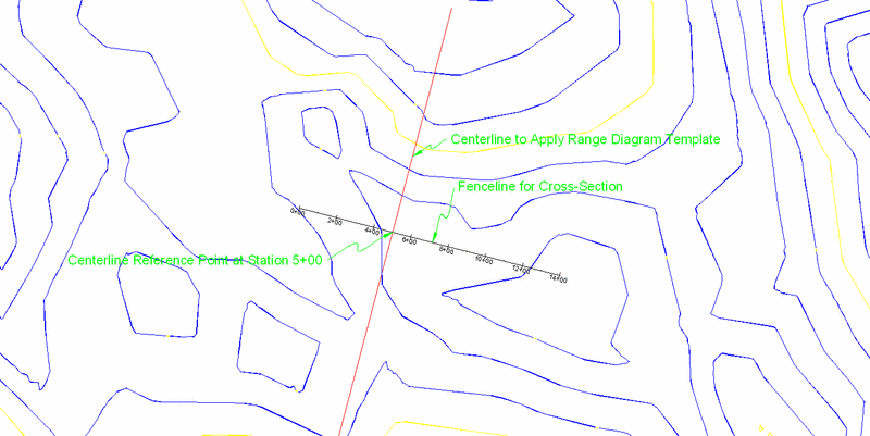
polylines drawn in plan view and sections. The first step is
drawing the fence line and intersecting it with the centerline for
laying out the cuts/pits as shown in the diagram below. This
intersection will be known in the commands as the centerline
reference point. Then draw the fence diagram with the hatching
turned off and draw as single polylines turned on. This will
provide an existing ground surface with the strata lines below it.
It is usually better if there is no exaggeration in the
cross-section.
Cut
& Place
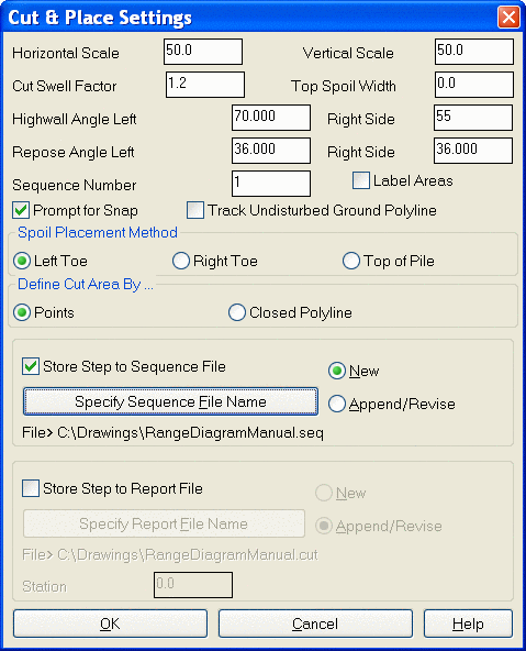
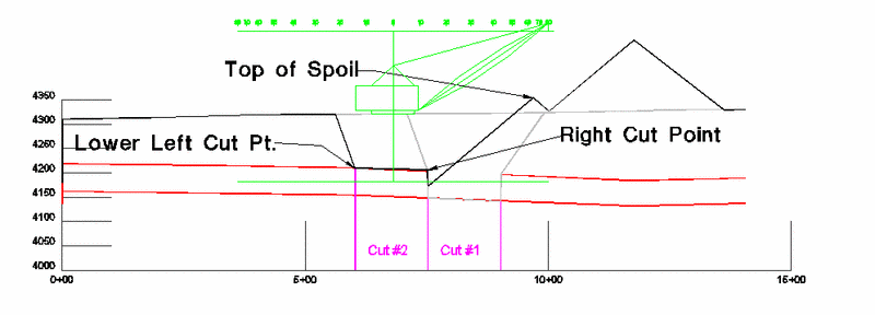
After drawing the dragline limits, the Cut & Place settings
need to be set as shown to the right. A 20% swell has been set, and
it will be stored to a new step file as shown with sequence number
one. This will be a simple box cut for the first sequence. Step two
will be the coal removal, and step three will be the next cut and
spoil placement. After step three, the sequence file will be
processed and turned into 3D polylines and a section file (*.sct).
The first step is shown below:
The first prompt after selecting the existing ground surface is to pick the centerline reference point. In this example, it is station 5+00 and it should be “snapped” to at the intersection of the horizontal grid line and the 5+00 tick mark. After selecting the top of strata polyline, you are prompted to enter the name of the strata. This name will be used later in prompting to select that surface grid file. Select the left and right cut points and the spoil location. Notice the two cuts were drawn in by hand to guide the user in the correct location of the cuts. This is sequence step number one.
Cut
Only (Coal Removal)
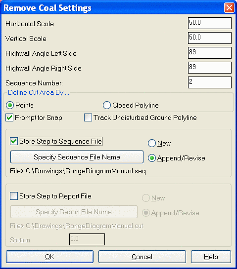
Step number two will be the removal of the coal block. The cut
angle will be set to 89 degrees on each side to simulate a near
vertical face of coal after it is removed. Try to stay away from
pure 90 degree slopes, as AutoCAD has difficulty sometimes. The
strata line will be the bottom of coal this time, and you will be
prompted to specify a name for that surface. (BOC for bottom of
coal works) You will also be asked to snap to the centerline
reference point (5+00).
Cut
& Place
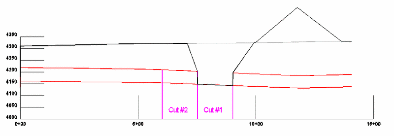
The third and final operation in the sequence will be the second
cut with spoil placement into the first cut. Everything is about
the same except for the sequence number needs to be set to three,
and it should change automatically. Shown is the final result, sort
of a template that will be applied now to our centerline (*.CL
file) utilizing the surface grids and create a new surface for
possible PMT application.
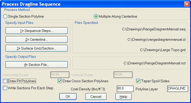
Process Dragline
Sequence
If it has not already been done, use the routine Polyline to
Centerline File to create the *.CL necessary for the processing of
the sequences. The following window will appear, and needs to have
at least the first three files set. It will also create an output
section file for later manipulation. The Taper Spoil Sides will
taper the ends of the spoil gradually down to the existing ground.
The draw pit polylines will create new pit/cut polylines to run for
scheduling. After selecting OK, you will be prompted for the grids
representing the strata named in the previous routines.
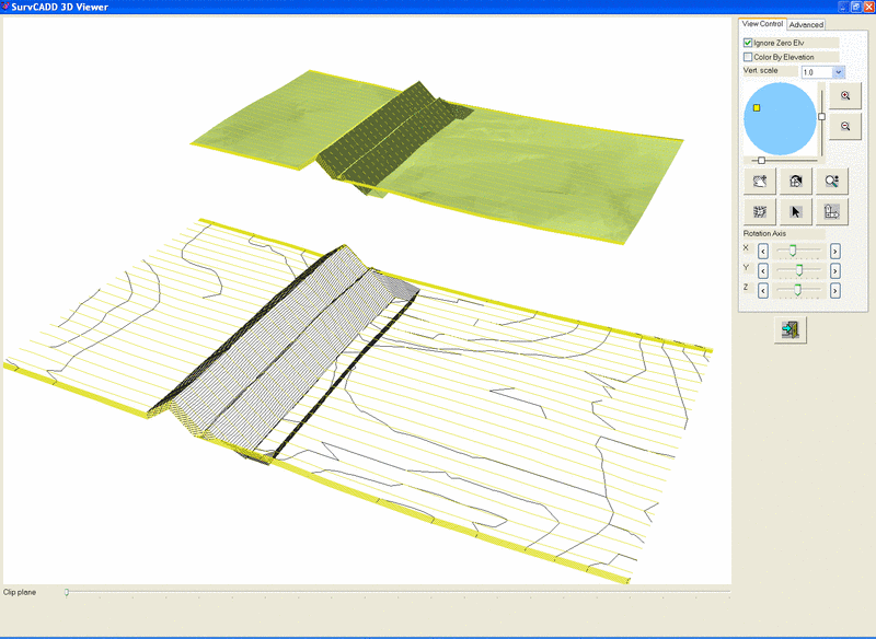
Shown below are two 3D views of the cross section lines that were automatically drawn at the specified 100- foot interval. For visual clarification, the 3D polylines were also contoured to begin building the new surface. Notice the pit is only as long as my centerline was drawn. The top image is a rendered image of Triangle Faces that were drawn.
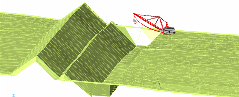
Another nice feature is to draw a 3D dragline and place it in plan view. This dragline shown was simply drawn with AutoCAD 3D faces and moved to the plan view. It gives good presentation material.
Draw Section
File
Another step is to draw the section file created in the processing
of the sequence. Shown is a partial series of sections created with
the Carlson Range Diagram routines.