Scenes are 2D or 3D displays of various data types in the viewer. Multiple objects can be viewed in a single scene or you can set each item is an independent scene.
To create a scene with Point Clouds:
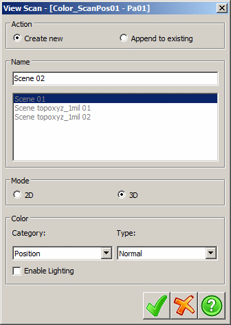
The View Object dialog will be displayed.
 Note:
One exception is if you right-click an existing scene and
select view, Point Clouds will display the
selected scene in the viewer.
Note:
One exception is if you right-click an existing scene and
select view, Point Clouds will display the
selected scene in the viewer.
The Action panel determines whether to create a new scene for the object or to append the object to a scene that already exists.
| Create new: | Enter the name in the Name edit field for the new scene. |
| Append to existing: | A list of existing scenes will become enabled to allow selecting the target scene. If there are no existing scenes The Append to Existing option will be grayed out. |
The name edit field and the list of existing scenes are used to assign the name of the scene for the object to be viewed.
The Mode panel determines the dimensions to view the data in, 2D or 3D. Viewing the data in 2D mode will only be available if the dataset can be laid out on a two dimensional plane (scans, profiles, and images). Additionally, selecting 2D mode will not add a new scene to the project, it will only create a temporary scene to view the data in, because there is no reason to view multiple objects in the same 2D view (the objects would all obscure each other).
The Color panel determines the mode to color the data in. There are eight color modes. The available modes depend on the data selected for viewing and the mode it will be drawn in. These color modes are divided up into categories based on how the colors are determined, these categories are:
| Category | Type |
|---|---|
| Simple: Colors the entire dataset the same color | Direct: Colors the entire dataset a single color. The color can be chosen in the Scene tab of the Project Manager. |
| Position: Colors each point based off its world positioning data. | Elevation: Colors each point in a range from
blue being the minimum elevation value to red being the maximum
color value. Range: Colors each point based off its distance from the origin (or scanner if the current object being viewed is a scan), black being the minimum distance and white being the maximum. Normal: Colors each point based of the normal of the surface at that point. In the Normal mode, each color dimension (red, green, and blue) are assigned a spatial dimension (x, y, and z) to represent that direction in the objects finally color. |
| Intensity: Colors each point based off of its single intensity value. | Direct: Color each pixel in the range from
black to white based off its intensity value. Scaled: Scale the range of intensities so that the minimum intensity in the data set matches up with zero and the largest intensity in the data set will match up with the maximum possible intensity value, which can make minor changes in intensity more noticeable. Equalized: will perform a similar scaling operation but do it in a manner that will equalize the histogram of the intensity values, making it so that all intensity values occur equally often, this method can also make minor changes in the intensity much more noticeable. |
| Color: Colors the points based off their color information. | Direct: Colors each point directly by its
internal color value. Grayscale: Colors each point by the grayscale representation of its internal color value. |
In addition to the above method of scene creation, you may also create a scene by right clicking the scenes folder and selecting Add ⇒ New from the menu. This method will allow you to create a scene with multiple objects in it without having to go through the dialog several times.
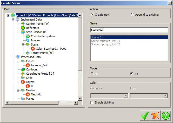
The right half of the dialog is the same as single object viewing, but the left half of the dialog shows a tree structure representing objects in the project that can be added to the scene. Click on the red x icon next to an object to toggle inclusion of that object in the scene.
Note: When viewing any of the large
object types (scans, meshes, and clouds) there is only one copy of
that object retained in memory at all times. This is done to
preserve memory as much as possible when opening up multiple views
of the same object. This also means that any changes made to the
object in one view will be reflected in all other views of that
object. For instance, if you're viewing a scan in two views and
wish to clean up its data, deleting points from the scan in one
view will change the scan in any other views of it. When all views
of an object have been closed, the object modified dialog will be
displayed prompting the user for an action to perform with the
modified data.
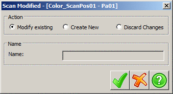
This dialog is very similar to the one used in the Action tab
when edits are made there.
Modify existing will save the changes to the
original object.
Create new will create a new object to save the
modified data to and is typically the safer option because the
original data is still available if needed.
Discard Changes will close the scene without
saving the changes leaving the scan unaltered.