Grass Channel Design
This feature allows you to design grass lined channels having one
of three different cross sections:
1. Triangular
2. Parabolic
3. Trapezoidal
The design methodology that is used is that recommended in Chapter
7, Grass Waterways, Part 650 of the Engineering Handbook published
by the United States Department of Agriculture Natural Resources
Conservation Service. It uses the equations found in Appendix
B of Chapter 7. The solution of the equations is an iterative
process and results in several possible cross sections having
varied dimensions. The designer must then use engineering
judgment to choose the final channel cross section dimensions based
on the site layout, machine crossing restraints, excavation
equipment to be used, etc.
Required Input Data
Basic Design Parameters
Use the entries on the Basic Design tab (see below) to specify the
design methodology to use and the basic shape and limiting
dimensions of the cross section.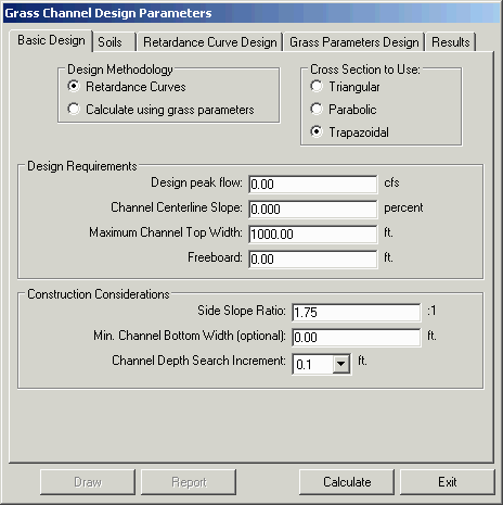
Design Methodology
You may use one of two available design methodologies:
1. Retardance Curves -
retardance curves can be used when specific data on the condition,
density, height and other information for the grasses being used to
line the channel are not available. This method will
generally result in a safe but relatively conservative
design. In this method the designer must specify one of
several available design curves (A through E) for the best and
worst grass conditions. (see the Retardance Curve Design tab
below)
2. Calculate using grass
parameters - this method requires the designer to have a
more detailed knowledge of the specific grass being used.
This allows the designer to produce a safe design that may not be
quite as conservative as the retardance curve method.
Cross Section to Use
Choose the type of cross section you prefer
1. Triangular
2. Parabolic
3. Trapezoidal
Design Requirements
Design Peak Flow - Enter
the Design Peak Flow (cubic feet or cubic meters per second) as
obtained from your watershed model or other source.
Channel Centerline Slope -
Enter the percent slope of the reach of the channel you are
designing.
Maximum Channel Top Width -
You may specify a starting maximum channel top width. This
value will limit the maximum top width that will be considered in
the design calculations. This should be set to match the
largest channel that your site could accommodate or the maximum
that is desirable.
Freeboard - Specify how
much freeboard you wish to add to the channel depth above the
design water flow depth. This is a matter of engineering
judgment and should, among other things, consider the consequences
of overtopping and the probability that that may happen. You
could estimate this value by doing a preliminary design using a
more severe flow than the actual design peak flow.
Construction Considerations
Side Slope Ratio - specify
the minimum slope ratio for the side slopes of the channel.
For a parabolic channel this will be the side slope ratio
calculated at the water surface. This should be set keeping
in mind construction limitations and what types of vehicles or
machinery must cross the channel, along with possible erosion due
to runoff, etc.
Min. Channel Bottom Width
(optional) - This field is only available in the case
of a Trapezoidal cross section. If this value is not
specified a minimum value of 1 foot (or 30 cm) will be
assumed. This value should be set to accommodate construction
equipment and can also effect ease of crossing by other vehicles or
machinery.
Channel Depth Search
Increment - This value is used to increment the depth of the
channel for the iterative solution and thus sets the significant
figures used during the design calculations and the resulting
design dimensions reported. This value should generally
reflect the elevation accuracy expected for the construction of the
channel cross section.
Soils
The Soils tab of the
Grass Channel Design
Parameters dialog allows you to specify the type of soil
encountered along the reach of the channel being designed.
Non-cohesive Soils:
If the soil is non-cohesive then check the Non-cohesive Soil check box (see
below). This means that the soil must have a Uniform Soil
Classification System (USCS) classification of GW, GP, SW or SP
(well or poorly graded gravel or sand) with a Plasticity Index (PI)
that is less than 10.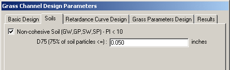 When the Non-cohesive Soil check box is checked
the D75 (75% of soil particles
<=) edit box appears. Specify the opening size (in
inches or millimeters) of the sieve that 75% of the soil particles
will pass through.
When the Non-cohesive Soil check box is checked
the D75 (75% of soil particles
<=) edit box appears. Specify the opening size (in
inches or millimeters) of the sieve that 75% of the soil particles
will pass through.
Cohesive Soils
If the soils have a significant clayey or silty portion and have a
PI >= 10 then the Non-cohesive
Soil check box should be unchecked (as shown
below).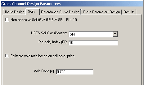 USCS Soil
Classification - choose the correct USCS classification of
the soil in this reach of the channel from the drop down list
USCS Soil
Classification - choose the correct USCS classification of
the soil in this reach of the channel from the drop down list
Plasticity Index (PI) -
type in the PI.
Estimate void ratio based on soil
description - if this checkbox is checked the void ratio
will be estimated from the soil description (see below). If
it is unchecked the user must specify the void ratio.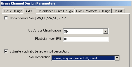 Void
Ratio (e) - enter the void ratio for the soil along this
reach of the channel. (shows only if Estimate void ratio based on soil
description checkbox is unchecked)
Soil Description - choose
the description that best fits the soils encountered along this
reach of the channel. (shows only if Estimate void ratio based on soil
description checkbox is checked)
Void
Ratio (e) - enter the void ratio for the soil along this
reach of the channel. (shows only if Estimate void ratio based on soil
description checkbox is unchecked)
Soil Description - choose
the description that best fits the soils encountered along this
reach of the channel. (shows only if Estimate void ratio based on soil
description checkbox is checked)
Retardance Curve Design
If you chose the Retardance Curves
Design Methodology on the Basic Design tab, then you use
this tab to specify the best and worst grass conditions for the
design.
Note: If you have chosen
the Grass Parameters Design
Methodology and you click this tab, you will only see
the message:
*** Using Grass Parameters Design Method
***
in the middle of the window.
Retardance Curve for Best Grass Condition
From the drop down list, choose A, B, or C retardance curves to be
used for the best grass condition. This condition will
control the minimum design depth of the water since grass in its
best condition will offer more resistance to flow and cause the
water to flow deeper. If you are unsure of which retardance
curve to use, choose any one of the curves and read the grass
descriptions in the window below the drop down list, then choose
the one that fits the expected best site conditions.
Retardance Curve for Worst Grass Condition
Use the drop down list to choose the retardance curve (C, D, or E )
to be used for the worst grass condition. This condition will
control the maximum design depth of the water since grass in its
worst condition will offer less resistance to flow and it or the
soil may be damaged by flows above this maximum level. If you
are unsure of which retardance curve to use, choose any one of the
curves and read the grass descriptions in the window below the drop
down list then choose the one that fits the expected worst case
site conditions.
Grass Parameters Design
If you chose the Calculate using
grass parameters Design Methodology on the Basic Design tab, then you use
this tab to specify the grass parameters for the best and worst
grass conditions for the design.
Note: If you have chosen
the Retardance Curve Design
Methodology and you click this tab, you will only see
the message:
*** Using Retardance Method for Design
***
in the middle of this window
When using the Grass Parameters design method you may choose to use
one of three methods to specify the cover factors (CF) for the best
and worst grass conditions. Cover Factors describe the
ability of the vegetal cover to reduce the maximum hydraulic stress
on the soil and is related to the type and quality of the vegetal
cover. The three available options are described below.
Estimate Cover Factors from
general grass description
When you click the Estimate Cover
Factors from general grass description radio button, the
items that are visible in the dialog are as shown below: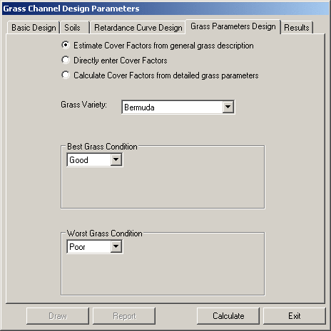
Grass Variety - choose the
grass variety that will be used to line the channel. If you
cannot find the variety you wish to use in the list then choose
Other (at the bottom of the
list). 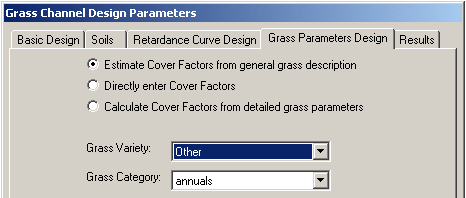 Grass
Category - choose the general category of the grass to be
used to line the channel. (this item only shows if you chose
Other as the Grass
Variety)
Grass
Category - choose the general category of the grass to be
used to line the channel. (this item only shows if you chose
Other as the Grass
Variety)
Best Grass Condition
Choose the condition category that
describes the expected best grass condition.
Worst Grass Condition
Choose the
condition category that describes the expected worst grass
condition.
Directly enter Cover
Factors
When you click the Directly enter
Cover Factors radio button the items visible in the dialog
are as shown below: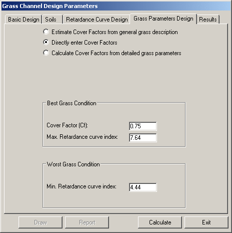 Best Grass Condition
Cover Factor (Cf) - Enter the cover
factor for the expected best grass condition.
Max. Retardance curve index
- enter the maximum retardance curve index for the expected best
grass condition.
Worst Grass Condition
Min. Retardance curve index - enter the
minimum retardance curve index for the expected worst grass
condition.
Note: The retardance curve
index values for the various SCS retardance classes have been
published in the publication quoted in the first
paragraph of this help item and can
be used to estimate the retardance curve index to use:
retardance Class
retardance curve index
(Ci)
A
10.0
B
7.64
C
5.60
D
4.44
E
2.88
Calculate Cover Factors from detailed grass parameters
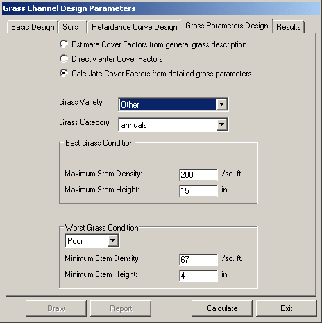 Grass
Variety - use the drop list to specify the grass variety to
be used to line the channel. If none of the varieties listed
are suitable you can choose Other.
Grass
Variety - use the drop list to specify the grass variety to
be used to line the channel. If none of the varieties listed
are suitable you can choose Other.
Crass Category - choose the
general category of the grass to be used to line the channel.
(only appears if Grass Variety chosen is Other)
Best Grass Condition
Maximum Stem Density - enter the
estimated stem density for the best grass condition
Maximum Stem Height - enter
the estimated stem height for the best grass condition
Worst Grass Condition
Use the drop down list to choose the
condition category that best fits the expected worst grass
condition.
Minimum Stem Density -
enter the estimated stem density for the worst grass condition
Minimum Stem Height - enter
the estimated stem height for the worst grass condition
Completing the Design Calculations
Once you have specified the basic design, soil, and grass
parameters you can click the Calculate button. If no data
entry errors are detected, the input data and the resulting channel
design(s) will be listed on the Results tab.
Results
After the design calculations have been made, the input data and
the resulting channel design information will be listed on the
Results tab.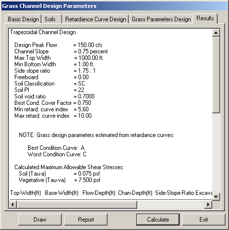 To view
the channel design cross section information in this window, you
merely left click on the scroll bar, hold the mouse button down and
drag the scroll bar downward.
To view
the channel design cross section information in this window, you
merely left click on the scroll bar, hold the mouse button down and
drag the scroll bar downward.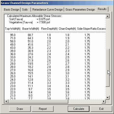 The Results listing starts with a recap of
the design parameters and the resulting calculated maximum
allowable stresses for the soil and the vegetation. Below
that begins a list of channel configurations that satisfy the
specified design parameters and thus will safely carry the design
peak flow (with some freeboard - if specified). The channel
geometry is described in six columns for a trapezoidal channel and
in five columns for both triangular and parabolic (neither
triangular nor parabolic have a bottom width column). The
columns are labeled: Top-Width, Base-Width (only for trapezoidal),
Flow-Depth, Chan-Depth, Side-Slope-Ratio, and Excavated-Area.
The units will be specified according to the unit settings
specified in Carlson Configure or CG Options. The Flow-Depth
and the Chan-Depth will only differ if freeboard is not zero.
The Results listing starts with a recap of
the design parameters and the resulting calculated maximum
allowable stresses for the soil and the vegetation. Below
that begins a list of channel configurations that satisfy the
specified design parameters and thus will safely carry the design
peak flow (with some freeboard - if specified). The channel
geometry is described in six columns for a trapezoidal channel and
in five columns for both triangular and parabolic (neither
triangular nor parabolic have a bottom width column). The
columns are labeled: Top-Width, Base-Width (only for trapezoidal),
Flow-Depth, Chan-Depth, Side-Slope-Ratio, and Excavated-Area.
The units will be specified according to the unit settings
specified in Carlson Configure or CG Options. The Flow-Depth
and the Chan-Depth will only differ if freeboard is not zero.
Note: If no safe design is
possible for the specified input parameters the following message
will appear below the column titles:
**
No valid channel cross section can be determined given specified
parameters **
Viewing, printing and/or saving the design report
To view the design report click the Report button. The report will
come up in the Carlson Editor, an example of which is shown
below.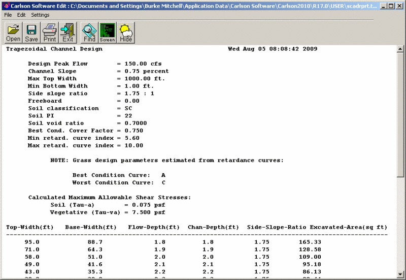 You can now view the input data and the results
as well as save them to a text file and/or print them.
You can now view the input data and the results
as well as save them to a text file and/or print them.
Draw the design channel cross section
Once the design calculations have been completed and the Results
tab is showing, review the available channel geometries and choose
the design you wish to use. To choose a design to be drawn to
the current drawing, highlight the desired geometry on the Results
tab as shown below: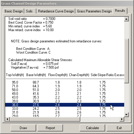 After highlighting a specific design
geometry by clicking on that line, click the Draw button to draw
the channel cross section in the current drawing. This will
bring up the Draw Grass Channel
Settings dialog (see below).
After highlighting a specific design
geometry by clicking on that line, click the Draw button to draw
the channel cross section in the current drawing. This will
bring up the Draw Grass Channel
Settings dialog (see below).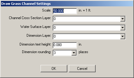
Draw Grass Channel
Settings
Scale - enter the scale at
which the channel cross section is to be drawn. This may
default to the current scale of your drawing but may be changed to
a larger or smaller scale.
Channel Cross Section Layer
- specify the layer on which the channel cross section lines are to
be drawn. You may choose an existing layer by using the drop
down list or you may specify a new layer by typing it in. If
you specify a layer that does not currently exist, the layer will
be created.
Water Surface Layer -
specify the layer on which the water surface line is to be
drawn. You may choose an existing layer by using the drop
down list or you may specify a new layer by typing it in. If
you specify a layer that does not currently exist, the layer will
be created.
Dimension Layer - specify
the layer on which the channel dimensions are to be drawn.
You may choose an existing layer by using the drop down list or you
may specify a new layer by typing it in. If you specify a
layer that does not currently exist, the layer will be created.
Dimension text height -
specify the height in plotted inches.
Dimension rounding - use
the drop down list to specify the number of decimal places to be
used for the dimensions.
Once the settings have been specified, click the OK button to proceed with the drawing
or Cancel to return to the
Grass Channel Design
Parameters dialog
If you clicked the OK
button you will be returned to the drawing with the following
command line prompt:
Pick location for channel cross
section drawing: pick a point on the screen for the upper
left hand edge of the cross section.
The channel cross section will then be drawn (see an example below)
and you will be returned to the Grass Channel Design Parameters dialog
where you can choose to draw another cross section from the current
design list or enter the design parameters for a redesign of the
current reach or the design of another reach of this or another
channel alignment.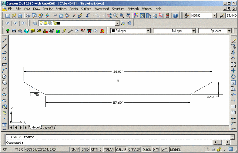 When all designs are completed and you wish to
close the dialog, click the Exit button.
When all designs are completed and you wish to
close the dialog, click the Exit button.
Prompts
Use the dialog as described above.
When drawing the cross section, this prompt will appear:
Pick location for channel cross
section drawing: pick a point on the screen for the upper
left hand edge of the cross section.
Pulldown Menu Location:
Hydrology Menu - Structure > Channel Design > Grass
Keyboard Command:
cg_grass_chan
Prerequisite:
None