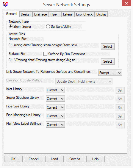
This command sets up the working environment for the design and analysis of sewer, sanitary and utility networks and should be done before starting the construction of networks.
Network Type: Indicate if the sewer network conveys storm runoff flow (Storm Sewer) or man-made flow (Sanitary/Utility). If the Sanitary/Utility network type is specified, the controls found in the Drainage tabare disabled.
Active Files: Select a new or existing sewer (.SEW) file to become the active sewer file and a "surface file" for ground cover calculations:
Link Sewer Network to Reference Surface and Centerlines: Indicate the method of how the sewer network should react if there are changes to either the specified Surface Model or any related Centerlines that are specified in either the Create Sewer Structurecommand or the Edit Sewer Structurecommand. The following types of corrections can be made:
Depending on the desired level of end-user control vs. automation, one of the following corrective options can be specified:
Elevation Update Method: Indicate how the invert elevation(s) should change as a result of a change to a Surface Model (when the "linking" method is set to Auto):
The Inlet Library, Sewer Structure Library, Pipe Size Library, Pipe Manning's N Library, and Plan View Label Settings can be set to the current project file CURRENT or SPECIFIC. If specific is specified the user can SET the location of the library files to be used.
The SaveAs button saves all the settings to a .SNS file and Load
button loads all the settings from a previously saved .SNS file.
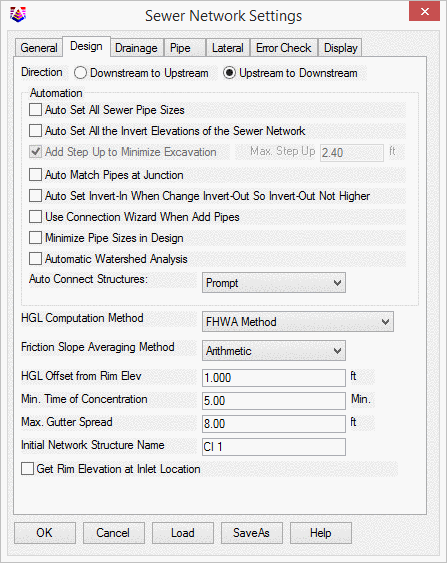
Direction: The network can be designed from Downstream to Upstream or vice versa. If the design direction is from Downstream to Upstream, the first structure created is generally the outfall and the current structure and its downstream pipe are highlighted in the plan view. Otherwise, the network is created from one of its entrances toward the eventual outfall and the current structure and one of its upstream pipes are highlighted.
Auto Set All Sewer Pipe Sizes: When enabled, this option disables the Pipe Sizecontrol found on the Pipe tabof the Create/Edit Sewer Structurecommand and sizes the pipe(s) automatically to the closest available pipe size as specified in the Pipe Size Library.
Auto Set All the Invert Elevations of the Sewer Network: When enabled, this option:
Add Step Up to Minimize Excavation: When enabled, this option allows pipe inverts to be placed above the current invert elevation up to the Max. Step Upvalue to minimize excavation and create a potential "drop manhole."
Auto Match Pipes at Junction:
When enabled, this option sets the pipe
inverts automatically when creating a new pipe in order to match it
to other pipes at the same junction.
Auto Set Invert In When Change Invert Out So
Invert Out Not Higher: When enabled, this option will adjust the
invert in to the pipe to be higher than the invert out.
Use The Connection Wizard When Add Pipes: This
will open the pipe connection wizard when the user selects the ADD
or PICK an available pipe connection on the docked dialog box under
the Pipe Tab.
Minimize Pipe Sizes in Design:
When enabled and if the sewer network is being
designed, this option will ensure the pipes are not oversized as
extra calculation iterations are performed.
Automatic Watershed Analysis:
When enabled, this option performs an
automatic watershed analysis of the referenced
Surface Filefound on the
General tabto determine the drainage area
serviced by the new structure. This action is the same as clicking
the
Drainage Area - Calcbutton found on the
Drainage tabof the
Create/Edit Sewer Structurecommand.
Auto Connect Structures:
This option determines how to connect a newly
created structure to the network:
HGL Computation Method:
There are three methods to calculate HGL and
EGL: FHWA Method, Virginia DOT Method and Just Full Capacity - Ohio
Method. The differences are shown below.
The complete description can be found in "Drainage of Highway
Pavement (HEC12) form the FHWA Hydraulic Engineering Circular 12.
In this method, when the HGL at the downstream is above the
critical depth, use the HGL elevation as the initial elevation and
conduct non-uniform flow calculation; when the HGL is below the
critical depth and normal depth is above critical depth
(subcritical flow), set the HGL at critical depth and conduct
non-uniform flow calculation; when the HGL is below the critical
depth and normal depth is below critical depth (supercritical
flow), set the HGL at normal depth and conduct uniform flow
calculation. VDOT method is a simplified FHWA method. The first difference is
the determination of the HGL at the downstream side of the pipe. In
determining the HGL, begin with the actual tailwater elevation or
an elevation equal to 0.8 times the diameter of the outlet pipe,
whichever is higher. The second difference is that because the HGL
is always greater than critical depth, non-uniform flow is conduct
through all the pipes. Another difference is the velocity is normal
flow velocity.
One difference between FHWA method and this method is the
optimal pipe size. The optimal pipe size is based on the smallest
diameter pipe in which the design discharge for the selected storm
frequency will not exceed the just full capacity of the pipe. This
storm frequency is called Just Full Capacity Frequency. Just full
capacity with a free water surface is considered to occur at 93.8%
of the pipe diameter for circular conduits. Another difference is
the determination of the HGL at the downstream side of the pipe,
this method uses the tailwater elevation or critical depth plus
half of the diameter of the pipe, whichever is greater, to
determine the starting HGL.
Friction Slope Averaging Method:
Available methods are:
HGL Offset from Rim Elev:
This value is used to check the hydraulic
grade line result. If some of the hydraulic grade lines are within
this value from the rim elevation, alerts are presented to indicate
the potential problem(s).
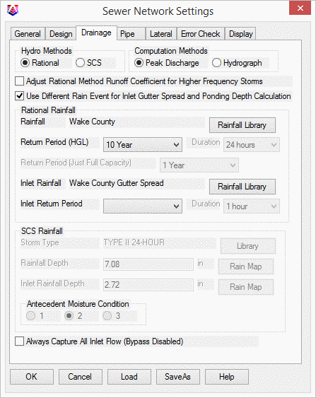
The drainage settings are used to set up the hydrology
calculation method and rainfall information for the design of Storm
Sewer networks.
Hydro Methods:
Select either the Rational method (the SCS
Rainfall group becomes disabled) or SCS method (the Rational
Rainfall group becomes disabled) for Peak Discharge
calculations.
Computation Methods:
Indicate the computation method for the Storm
Sewer network:
Adjust Rational Method Runoff Coefficient for Higher Frequency
Storms this option would time the runoff coefficient with a
constant to adjust the runoff coefficient. The constant for 25 year
is 1.1, 50 year is 1.2 and 100 year is 1.25. The adjusted runoff
coefficient is checked to make sure it's not greater than 1.0
Use Different Rain Event for Inlet Gutter
Spread and Ponding Depth Calculation:
When enabled, this option enables an alternate
rainfall event for either Rational or SCS calculation methods to
determine inlet efficiency.
Rational Rainfall:
Specify the Rainfall, Return Period and
Duration (if using the Hydrograph method) if using the Rational
equation.
SCS Rainfall:
Specify the Antecedent Moisture Condition,
Storm Type and rainfall map if using the SCS methodology.
Always Capture All Inlet Flow (Bypass
Disabled):
You may elect to let the inlets to capture all
drainage runoff.
Min. Time of Concentration:
This value will replace any calculated T
cthat is shorter than this value.
Max. Gutter Spread:
Indicate the largest allowable gutter spread
for determining inlet effectiveness.
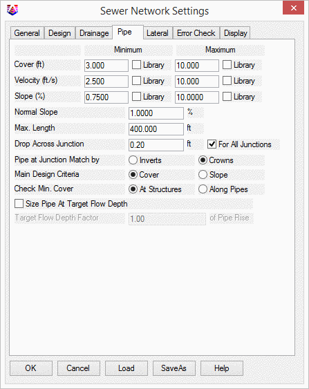
Cover:
Enter the minimum and maximum depth of cover
which is the distance from the surface elevation to the crown
elevation along the pipes. Alternatively, enable either (or both)
Librarytoggle(s) to use the value(s) specified in the
Pipe Size Library.
Velocity:
Enter the minimum and maximum flow velocity
for the pipes. The minimum velocity is about 2 to 3 ft/s (0.6 to
0.9 m/s) when the pipe is flowing full for self-cleansing. The
maximum velocity should be less than approximately 15 ft/s (4.5
m/s) to prevent erosion of the pipe interior by suspended sediment
and debris. Alternatively, enable either (or both)
Librarytoggle(s) to use the value(s) specified in the
Pipe Size Library.
Slope:
Enter the minimum and maximum slope range for
the pipes in the network. The minimum slope should be sufficient to
maintain the minimum velocity and the maximum slope is related to
the maximum velocity. Alternatively, enable either (or both)
Librarytoggle(s) to use the value(s) specified in the
Pipe Size Library.
Normal Slope:
The normal slope is the initial slope used to
place a pipe in the network.
Max. Length:
This is the maximum length between structures
in a network before an alert is presented indicating a potential
problem.
Drop Across Junction:
This is the drop across the inside of a
junction. Depending on the
Directionspecified on the
Design tab, the Invert Up is either raised by
this amount or the Invert Down is lowered by this amount.
Pipe at Junction Match by:
Indicate if pipes should be aligned by their
inverts or crowns.
Main Design Criteria:
Indicate which criteria should be maintained
if both the
Minimum Coverand
Minimum Slopecannot be satisfied. If
Coveris selected, the Slope will yield and vice
versa.
Check Min. Cover:
Define whether to check the minimum cover at
the structures only or along the entire length of each pipe.
Size Pipe At Target Flow Depth:
When this option is enabled in design mode,
the sewer pipes will be set to the sizes that are sufficient to
maintain the target flow depth.
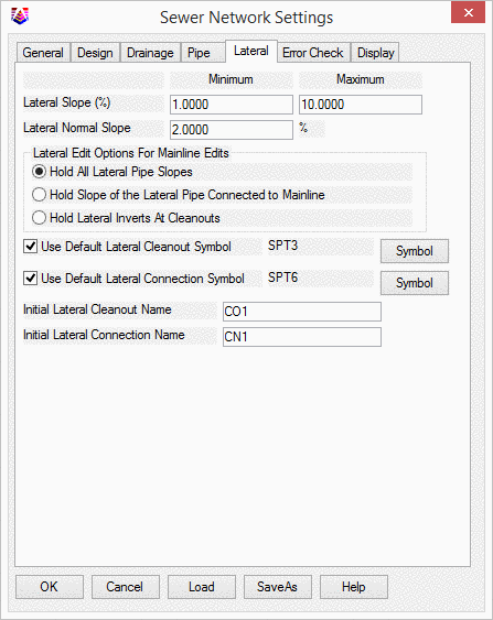
Lateral Slope:
Allows the user to set a minimum and maximum
lateral slope.
Lateral Normal Slope:
The normal slope is the initial slope used to
place a lateral in the network.
Hold All Lateral Pipe Slopes: This option sets
how the lateral should change if mainline edits are made, and will
hold the lateral slopes should the mainline be adjusted. Therefore
both the connection and the cleanout elevation would change to hold
the slopes.For more than one cleanout, all lateral slopes
are preserved after modifying the main line pipe.
Hold Slope of the Lateral
Pipe Connected to Mainline: This
option will adjust the first cleanout and lateral elevation if
the mainline is adjusted. Hold Lateral Inverts At Cleanouts: This option will adjust the lateral connection to
the mainline pipe and the cleanout invert would remain at the
original elevation. Use Default Lateral Cleanout Symbol: Allows
the user to select a symbol to be used as designation of the
cleanout. Use Default Lateral Connection Symbol:
Allows the user to select a symbol to be used as designation of
the connection Initial Lateral Cleanout Name: The user can
specify the initial cleanout name. A sequential numbers will
start from this setting. For example CO1, CO2, CO3, etc. Initial Lateral Connection Name: The user
can specify the initial connection name. A sequential numbers
will start from this setting. For example CONN1, CONN2, CONN3,
etc.
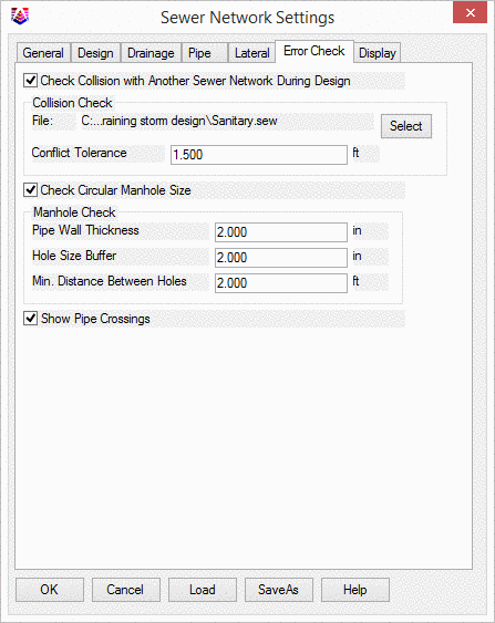
Check Collision with Another Sewer Network
During Design:
When enabled, this option allows for potential
conflict detection with another sewer network. Should the placement
of a structure or pipe encroach on the
Conflict Tolerance, an alert will be displayed to caution
against the potential collision.
Check Circular Manhole Size:
When enabled, this option will check if the
manhole is big enough to hold the incoming and outgoing pipes and
will display an alert if any of the settings are violated.
Show Pipe Crossings:
When enabled, this option allows you to
display the pipe crossings of current network opposed to any sewer
networks or pipes that are drawn in the drawing.
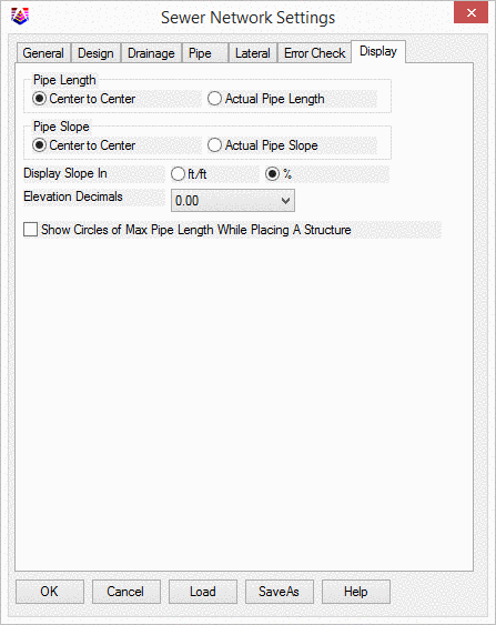
Pipe Length:
Specify how the pipe length should be
displayed.
Pipe Slope Annotation:
Specify how the pipe slope should be
displayed.
Display Slope In:
Specify to display slope in the unit of either
distance/distance or %.
Elevation Decimals:
Indicate the desired amount of precision to
display for elevation values.
Show Circles:Places circles
of max pipe length while placing structures.
Pulldown Menu Location(s):
Network > Sewer Network Setup
Drainage Settings
Pipe Settings
Lateral Settings
Error Check Settings
Display Settings
Keyboard Command:
swrconfig
Prerequisite:
None