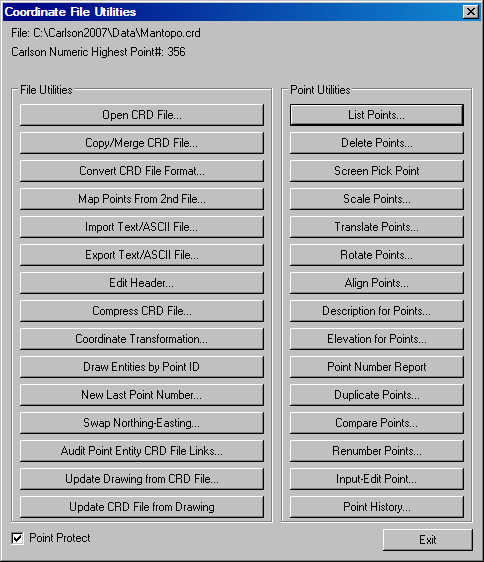
This command allows you to manipulate the coordinates stored in a coordinate (.CRD) file. One of the most important commands is the Update CRD File from Drawing which allows you to update the file after editing the drawing with commands such as Erase, Move, Rotate or Change Elevations. Another handy option is the Draw Entities by Point Number which allows the user to input point number ranges and plot Lines, Arcs, Polylines or 3D polylines. Coordinate files have either numeric or alphanumeric point numbers. Alphanumeric point numbers consist of nine or less digits and letters (i.e. point number 7A). The type of point number format is displayed at the top title bar of the main dialog. Another coordinate format is the Carlson coordinate database (.CRDB) which is based on SQLite and supports point numbers and descriptions up to 255 characters.
In addition to running the routines through the dialog, many
routines have command names that you can enter at the Command:
prompt, create a Quick Key, or put into a toolbar. Here are these
command names and their corresponding dialog button names:
Open CRD File: Allows the user to switch to another file. When you exit Coordinate File Utilities this will be the current file that you work with in Carlson.
Copy/Merge CRD File: This command allows for the copying
of entire CRD files, or parts of CRD files, to a new or existing
files. This can be used to make a backup of your coordinate file,
and it can also be very valuable in coordinate file manipulation.
For example, if a certain range of points from one CRD file was
also required in the active CRD file, this command would be used to
simply copy the required range into the active CRD file. There are
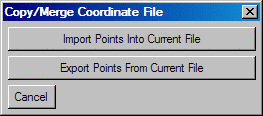
two options when first executing the command. These options are
whether to import points from another file to the current (active)
CRD file, or to export the current (active) coordinate file to
another file.
Once this option has been decided, a prompt for the file to copy
From or TO, will be displayed. Here simply specify the correct
file.
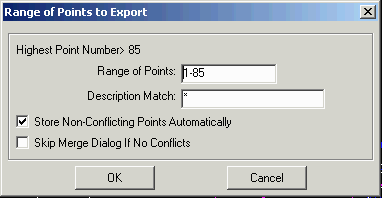
Next there's a dialog to specify the range of points to transfer
and some options. Here specify the points to copy. Point numbers
and ranges can be entered together, for example, 1-3,10,15 would
result in points 1 through 3 and points 10 and 15 being copied. The
Description Match can be used to filter the points to transfer only
the points with matching description. The default of * will
transfer all the points in the range. The Store Non-Conflicting
Point Automatically will set the transfer action as Store for all
transfer points that don't have a point protect conflict. The Skip
Merge Dialog If No Conflicts will skip the next dialog when there
are no point protect conflicts.
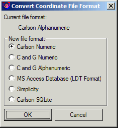
Convert CRD File Format: This allows you to convert the
current CRD file from numeric format to alphanumeric format or vice
versa. This routine will also change crd files to and from
different software formats. These formats include Carlson SQLite
(.CRDB), C&G, Microsoft Access (.MDB) in same format as
AutoDesk Land Desktop, and Simplicity (.ZAK). The current format of
the active coordinate file will be displayed as well as the options
for the new file format. This command only changes the format of
the active coordinate file.
Map Points from 2nd File: This routine adds point to the
current CRD file from points stored in a second CRD file. The
points to copy are specified by numbers one at a time. Prompts for
the destination point number (number to create in current crd file)
and source point number (point number to be copied from second crd
file) will be displayed.
Import Text/ASCII File: This routine converts point data from a text file into the current coordinate (.CRD) file. See the Import Text/ASCII File command in this chapter for more information.
Export Text/ASCII Text File: This routine outputs point data from the current coordinate (.CRD) file to a ASCII Text file. See the Export Text/ASCII File command in this chapter for more information.
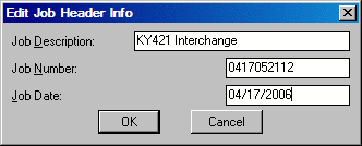
Edit Header: Enter or edit the job information associated
with the coordinate file. The fields include Job Description, Job
Number and Job Date. This information will appear on the List Point
report. Non-digit characters are not allowed in the Job Number
field.
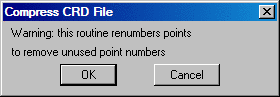
Compress CRD File: Removes unused point numbers by
renumbering high point numbers into the unused spaces. For example,
for an original file with points 1,2,105,107,108,109 would be
compressed to 1,2,3,4,5,6.
Coordinate Transformation: Transforms coordinates between
local, state plane 27, state plane 83, latitude/longitude,
Universal Transverse Mercator (UTM) and many other projections
including user-defined. Works on individually entered coordinates,
by range of point numbers and with on-screen entities. For
converting between state plane 27 and 83 within the USA, Carlson
calls upon NADCON from the National Geodetic Survey to apply the
latitude/longitude adjustment. Converting between NAD27 and NAD83
for Canada is supported using NTv2 grids.
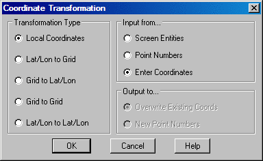
The Transformation Type is used to define the Source Coordinate
and Destination Coordinate formats. Settings for Lat/Long Datum,
Lat/Long formats (dd.mmss or dd.dddd), Projections, State Plane
Zones and coordinate units are defined in the Transformation Type
dialog. The format of this dialog will change depending upon the
type of transformation requested.
For Grid to Grid transformations, the program converts between
state plane projections as well as other pre-defined and
user-defined. When converting between pre-defined/user-defined
projections, the program automatically converts the source grid
coordinate to latitude/longitude and then to the destination grid
coordinate. This method of using latitude/longitude works for
converting between projections that share the same datum.
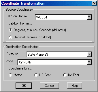
|
| Example Lat/Long to Grid dialog |
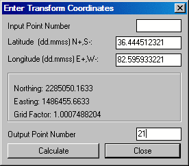
For all Transformation types, there are three options for
inputting the data to be transformed. Data can be selected from the
screen by using the Screen
Entities. If a range of points or a particular point is
desired, the Point Numbers
option would be used. Manual entry of coordinates to transform one
at a time is accomplished with the Enter Coordinates option. The
coordinates can be typed in or use the Input Point Number option.
Output Point Number is an option to store the results in the
coordinate file.
For all transformations there are two output options when using
point numbers as the input data. Overwrite Existing Coords replaces the
original coordinate values with the new coordinate values after
transformation. New Point
Numbers will retain the original coordinate data and point
numbers and create new point numbers with the revised coordinate
data after transformation.
When transforming a Local Coordinate System, there are two options for defining the transformation as shown in the next dialog.
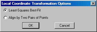
The Align by Two Pairs of Points option uses two pairs of source and destination coordinates. The first pair defines the translation as the difference between the source and destination northing and easting.
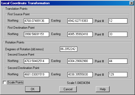
This destination point is also the pivot point for rotation. Rotation can be entered directly or defined by a second pair of points where the bearing between the first and second source points is rotated to align with the bearing from the first and second destination points. There is an option to also apply scaling. The scaling holds the angle between points and adjusts the distances by the scale factor. The scale factor is calculated for each point as the elevation factor at the first source point times the grid factor at the first destination point averaged with the elevation factor at the transform point times the grid factor at the transform point.
The Least-Squares
Best-Fit option is used when there are more than two pairs
for translation points. Since two pairs of points are sufficient to
define the translation and rotation, more than two pairs of points
provides more than enough information.
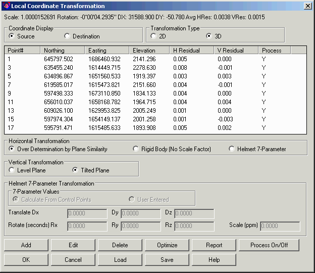
Over Determination by Plane
Similarity is used to find the least squares best fit
transformation for all the given source and destination points.
Besides doing a translation and rotation, this option will also
scales the points during the transformation. The Rigid Body Transformation also does a
best fit least squares transformation, but applies only translation
and rotation with no scale. The Helmert 7-Parameter method can also be
used for local transformations. The 7-Parameter Values can be calculated
from control points or entered by the user.
The Transformation Type chooses between doing a 2D
transformation and 3D transformation. For the 3D transformation,
the program transforms the x/y using the same method as the 2D
transformation, and the z is transformed using an elevation
difference model that is modeled by either a best-fit level plane
or tilted plane as set by the Vertical Transformation
setting.
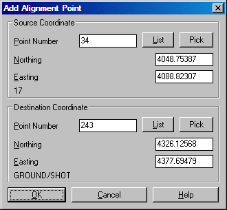
The Add button is used
to define the source and destination coordinates for the points
that define the transformation. Pressing this button brings up the
following dialog box.
The Edit button is used to edit existing data.
The Delete button removes the source and destination pairing from the transformation setup.
The Process On/Off
button allows source and destination pairings to be turned on and
off. This is useful when wanting to inspect different results using
different pairings.
The Optimize option
chooses which point pairings would yield the best transformation
results by turning off the processing of pairings with higher
residuals. This minimizes the average residual for the control
points.
The Report option
displays a report of the transformation point pairings, their
residuals, processing status, transformation scale and avg.
residual.
The Load and
Save options allow for
saving and recalling local coordinate transformation pairings and
settings.
Draw Entities by Point ID: Draw Lines, Arcs, 3DLines, Polylines or 3DPolys by defining a range of point numbers.
Plot Entities by Point Number
Type of entity, Arc/Polyline/3dpoly/2dline/Exit/<Line>:
P This response causes the program to plot polylines.
Example: `1*4-7-10*12-5-8' would draw lines from point number's
1 through 4 then to 7, to 10 through 12, then to 5 to 8. (limit 132
characters)
Undo/<Enter point numbers or ranges>:
1*10-20*30
The program draws a polyline from point number 1 through 10 to
point number 20 through 30.
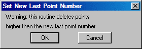
New Last Point Number: This option sets the highest point
number in the CRD file. All points above this number are
erased.
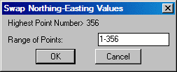
Swap Northing-Easting: This option allows you to swap
northing and easting coordinates for any selected range of points.
What was the northing of an existing coordinate point, or range of
points, becomes the easting. And the easting(s) becomes the
northing(s).
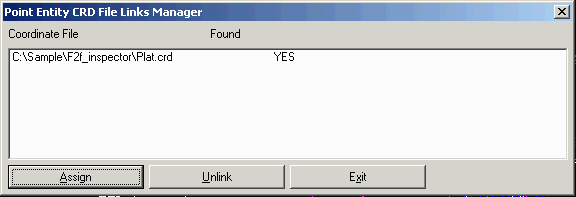
Point Entry CRD File Links Manager: When points are
created in the drawing, the program records the source coordinate
file for the points. The coordinate file names assigned to the
point entities links the point entities back to the coordinate
file. These links are used by routines that process the point
entities and then need to reference the coordinate file such as
Move Point which selects a point entity and updates the coordinate
file. This routine checks all the point entities in the drawing and
lists all the linked coordinate files. You can use the Assign
button to set the coordinate file assigned to point entities which
is useful when the coordinate file has been moved after the points
were drawn. Use the Unlink button to remove the link.
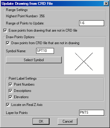
Update Drawing from CRD File: This function updates the
position of Carlson points in the drawing to match the position
stored in the coordinate file. This command also has options to
erase and draw points. For the erase option, points are erased from
the drawing if the point number does not exist in the coordinate
file. For the draw option, if a point number in the CRD file does
not exist in the drawing, then this point is drawn using the
settings from the dialog. The number of points modified, erased and
drawn is reported at the end of the command.
Update CRD File from Drawing: This function allows you to select all or some of the points in the drawing and add or update them to the .CRD file. The points can be filtered with AutoCAD's Select Objects: selection mechanism and/or wild card matching of the point descriptions. The Update Point Descriptions option determines whether the point descriptions from the drawing will be stored to the CRD file. Use this command to update the file after a global edit such as Move, Rotate, Renumber Points, Change Elevations, Erase, etc. This routine directly reads Leica (Wildsoft), Softdesk, Geodimeter, InRoads, Land Development Desktop, and Eagle Point point blocks.
List Points: List the points stored in the .CRD file. See the List Points command in this chapter for more information.
Delete Points: Deletes points in the coordinate (crd)
file by point number or description.
Screen Pick Point: Pick a point on the graphics screen and it's coordinate values are added to the coordinate (crd) file. Prompts for point number, elevation and description will be displayed. This command does not plot a point, point attributes or point symbol. Use the command Draw-Locate Points command to do this.
Scale Points: This option multiplies the point northing, easting, and elevation by the scale conversion factor. You can use this routine for metric-English conversion. See the Scale Points command in this chapter for more information.
Translate Points: This option translates a range of points based on entered delta x and delta y, entered coordinates or translation point numbers. See the Translate Points command in this chapter for more information.
Rotate Points: This option rotates a range of points based on entered degrees or rotation, entered azimuths, entered bearings or rotation point numbers. See the Rotate Points command in this chapter for more information.
Align Points: This option does a translate based on a source point and destination point and then rotates to align the first source point and a second source point with the first destination point and a second destination point. See the Align Points command in this chapter for more information.
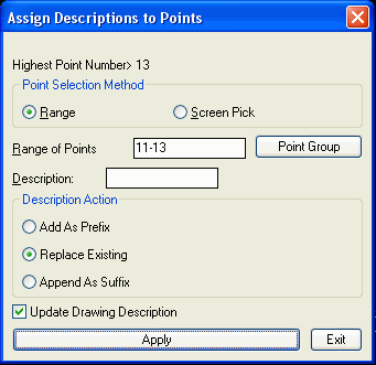
Description for Points: This routine modifies the point
description field with the user-specified text for a range of point
numbers. There is an option to update the description attributes of
the points in the drawing in addition to updating the coordinate
file.
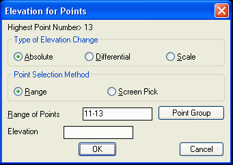
Elevation for Points:
This routine modifies the elevation of the specified points. The
Absolute method sets the elevations to the specified value. The
Differential method adds the value to the current elevations. The
Scale method multiplies the current elevations by the
value.
Point Number Report: This routine lists the used and the unused point numbers in the CRD file.
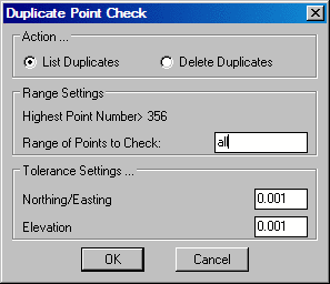
Duplicate Points: This function searches the CRD file for
points with the same northing, easting and elevation. The
tolerances for considering points to have the same coordinate are
set in the dialog separately for northing/easting and elevation. To
be counted the same coordinate, both the northing/easting and
elevation must be within the tolerance distance. The duplicate
points can be erased or only reported. For the erase option, the
first point number is kept and any higher point numbers with
duplicate coordinates are erased from the CRD file.
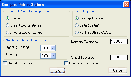
Compare Points: This function compares the coordinates in
the .CRD file with either the coordinates for the matching point
numbers in the drawing file, with matching point numbers from
another CRD file or with different point numbers from the same CRD
file. A report is created for any differences that shows the point
numbers and the differences. The difference can be reported as a
bearing and distance between the two points, as distance
North/South and East/West or as the delta-X and delta-Y. There is
an option whether to include the point coordinates in the report.
The Create Point Groups option creates point groups of "Missing
From Drawing" and "Changed Points" for any points that have this
status. Use the Point Group Manager routine to check on these point
groups.
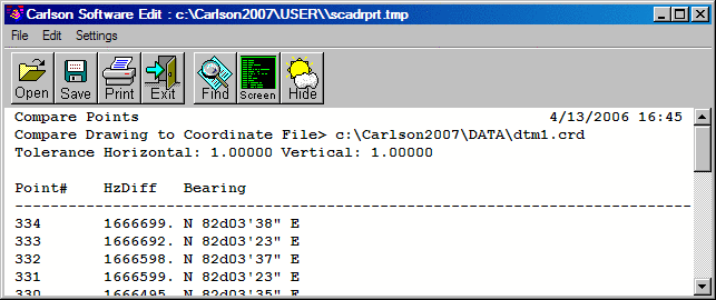
|
| Example Bearing-Distance format Compare Points Report |
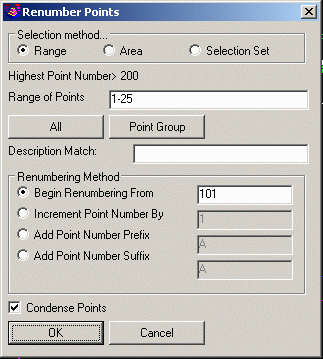
Renumber Points: This option renumbers points in the
user-specified range starting from a new point number. The old
point numbers are erased. The Area selection method prompts to pick
a closed inclusion and exclusion polylines. The Selection Set
method prompts to pick the points from the drawing. The Description
Match filters the points to renumber. The Condense Points will
renumber such that there are no unused point numbers in the
renumbered range. Otherwise the spaces between the points is
maintained. In the example shown, renumbering 1-25 with points
1,2,24,25 to starting point number 101 will result in points
101,102,103,104 if condense is on or 101,102,124,125 if condense is
off.
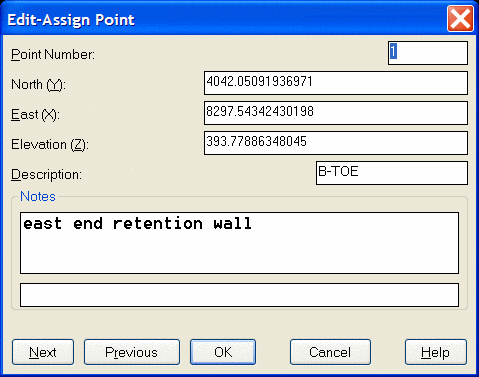
Input-Edit Point: Enter or edit the coordinate values or
the description of a point. The Notes section is for adding
optional point notes which are additional point descriptions. The
standard description field is limited to 32 characters. Under
notes, any number of lines of text can be assigned to the point. A
list box shows the lines of notes. To add a note line, pick a blank
line in the list box and then type in the note in the edit box
belong the list box and press Enter. To edit a note, highlight the
line in the list box and edit the text in the edit box.
Point History: All changes to the coordinate file will
record the commands performed on this coordinate file and the
status of the points themselves. This makes up the coordinate file
history. The history can then be reported by point number or by
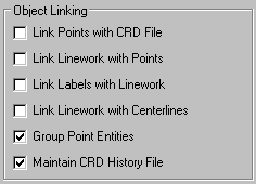
command. All of the changes can be rolled back. It is important to
note that if maintaining such a history file is your objective, in
the Settings > Configure > General Settings dialog you must
make sure that Maintain CRD History File is checked.
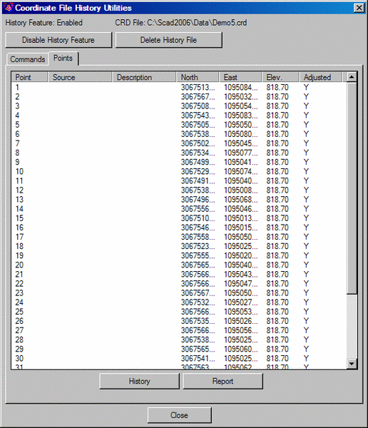
The Disable History Feature button at the top of the
dialog shown above is a toggle device. It should be clicked if you
prefer not to build the point history file. Clicking it a second
time changes it back to saying Enable History Feature. You
can also choose Delete History File to delete the file
altogether. By clicking any point from the list, as shown in the
Points tab example above, and then selecting History, you will be given the history
for that specific point. Double-clicking on any command shows the
details. Clicking on Details also shows the selected
command's details. Undo thru
Selected will undo the effect of all of the commands up
through and including the selected command. The changes from the
undo command are themselves then added to the command list and can
be undone in the future.
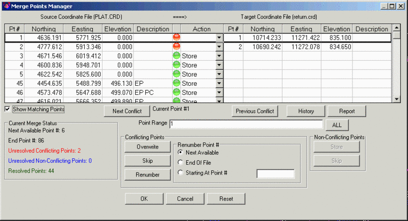
Point Protect Toggle: This option, located at the
bottom-left of the main Coordinate File Utilities dialog,
toggles point protection on and off. With this option on, when
attempting to store a point with a point identifier (point number)
that already exists in the current coordinate file, the following
dialog will be displayed.
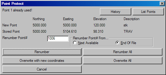
Overwrite with new
coordinates will update the existing point number with the
new location of the point.
The Use Another Number
field displays the point number that will be used if the Use
Another Number option is selected. This number will depend upon the
option chosen from the Another
Number From settings. If Next Available is chosen, the
next available number will be displayed in the Use Another Number
Field. If there are number gaps in the coordinate file this number
will not be the next highest number in the file. For example if
points 1-10 and 20-30 exist in the crd file leaving a gap from
11-19, the Next Available number would be 11. If the desired point
number, in this example, is 31, then the option of End of File would be selected.
The Overwrite All and Renumber All options apply when more than one point with the same number exists in the coordinate file. These options are helpful when importing points into existing CRD files.
Pulldown Menu Location: Points
Keyboard Command: cfu
Prerequisite: None