GIS Query/Report
This command applies a user-defined query on a data table or
related tables with the database. Records in the table that pass
the query can be reported or the associated entities can be
highlighted in the drawing. The Query Using option in the
main dialog box sets the source of the data table to process as
either GIS data attached to selected drawing entities or from the
current Output MDB file.
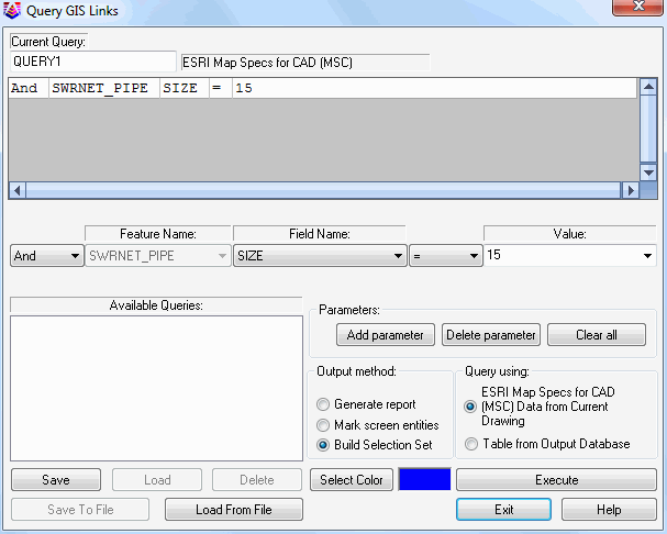 The query is defined in the dialog shown here. To
add a query, enter a new query name in the in the space underneath
Current Query. If there is already a name there, just highlight and
type over it with a new name, then hit Clear All to clear out
existing query lines and get full access to all Feature
Names.
The query is defined in the dialog shown here. To
add a query, enter a new query name in the in the space underneath
Current Query. If there is already a name there, just highlight and
type over it with a new name, then hit Clear All to clear out
existing query lines and get full access to all Feature
Names.
The top portion of the dialog contains a list of the query
parameters. To add a parameter, select a Feature Name from the
pop-up list. The available features will either be all the features
found in the GIS links of the drawing or all the features from the
Output MDB file depending on the Query Using option. Once
the feature is specified, the Field Name pop-up list contains all
the available fields in the feature. Choose a field from this list.
Next choose the operator (=, >, etc.) from the operator list.
The Value pop-up list contains all the different values for that
field that are found in the current data set. You can either select
one of these values or type in another value into this field. If a
Field Name relates to another Feature, when you select that Field,
an additional button will appear allowing you to add a query
parameter from the related feature.
 When all the parameter values are
set, pick the Add Parameter button. Once a feature is selected and
add a parameter is added, the Feature Names list becomes
unavailable because any additional query parameters must come from
that feature, or relate through that primary feature.
When all the parameter values are
set, pick the Add Parameter button. Once a feature is selected and
add a parameter is added, the Feature Names list becomes
unavailable because any additional query parameters must come from
that feature, or relate through that primary feature.
When all the parameters are defined for the query, you can save
these settings by filling out a name Current Query field and then
picking the Save button. This query can be recalled later by
highlighting the query name and clicking the Load button. The
Delete button removes the highlighted query. The Save, Load and
Delete functions operate on the current set of queries active in
the program. The Save To File and Load From File functions read and
write the collection of queries to a .QRY file for managing
different sets of queries and sharing with others.
Pick the Execute button to process the query. The Mark Screen
Entities option will set the color of entities with GIS data that
match the query to the specified color. The Build Selection Set
option creates a selection set of the entities that pass the query.
To use this selection set in other commands, enter "P" for previous
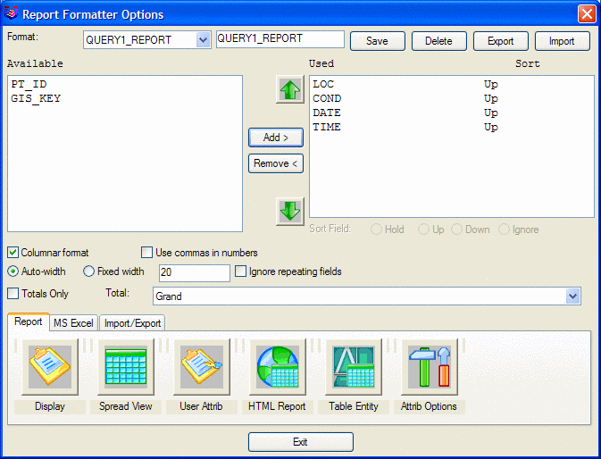
at the "Select objects:" prompt. With the Generate Report option,
the program will bring up the Report Formatter which allows you to
choose the fields to include in the report and the report format.
If the Highlight Screen Entities option is on, then the program
will highlight the entities with GIS data that pass the query.
Point entities are highlighted by drawing a box around the point
and polylines are highlighted by solid fill. Shown here is the
report for all manholes with a Condition of Good.
Pulldown Menu Location: GIS Data
Keyboard Command: gis_query
Prerequisite: MDB file with data or entities with linked GIS
information