Projections/Ventilation makes heavy use of specification files. Once parameters have been established for a set of projections within a drawing file, you can save those parameters to a specifications file. When changes or additions are necessary, simply erase any undesired projections, load the file, make changes, and process. The specification file contains all the information contained within the dialog, including the projection and ventilation parameters, mandoor and stopping information, even the layer names to use.
These files can reside in any directory (usually the same directory as the drawing), and have the extension (*.PVS). When the program is activated for the first time within a drawing session, it will look for a PVS file with the same name as the drawing, in the drawing's directory, and if found will load it. If a PVS file with the drawing's name is not found, it will look for a file named DEFAULT.PVS in \PROJECTIONS/VENTILATION subdirectory, and load it.
You can utilize this feature to your advantage by saving the general specifications about a particular drawing in a PVS file with the same name as the drawing. This way, if only the azimuth changed in a set of projections, you could open the drawing, activate Projections/Ventilation, change the azimuth, and process. You can also access the program's dialog box, enter and then store the specifications you would use most often across drawings as DEFAULT.PVS in \SCAD\LSP subdirectory.
Dialog Control:
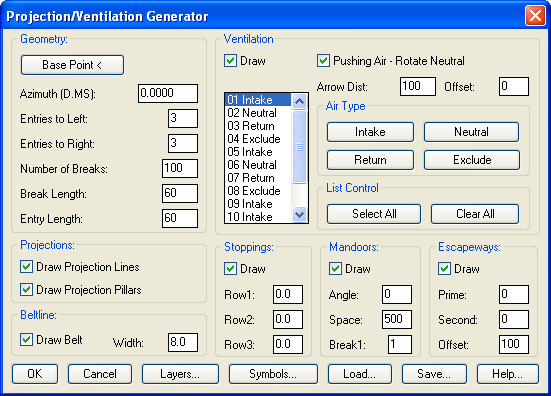
When Projections/Ventilation starts, it will display the dialog
shown below. All specifications can be entered inside this dialog,
and execution of the entity generation process can be initiated as
well. Each section of the dialog will be explained in detail in
appropriate subsections that follow.
All of Projections/Ventilation's options are accessed easily through this dialog with edit fields for parameters and buttons for each routine available in the program.
Geometry Specifications:
Before generating any entities using Projections/Ventilation, you
must specify the geometric specifications of base point, azimuth,
entries left/right, number of breaks, break and entry length.
Base Point: This button is used to specify the base point of the geometric entities. After picking this button, the dialog will temporarily disappear, allowing you full screen access to your drawing, and a prompt will appear at the command line requesting you to select a base point.
Choose the base point by picking or typing in coordinates. You MUST use an object snap (NODe, CENter, or INSertion) if picking the point graphically, to guarantee that the point selected is exactly on the point, spad circle, or insertion point of a point block.
Azimuth: This edit field is used to enter the projected azimuth. Enter the value in the format of DDD.MMSS, where the whole number of degrees are followed by a period, then minutes and seconds. If the minutes or seconds are less than ten (10), put a leading zero in front such as 01, 05, etc. If the minutes or seconds are zero, enter two zeros 00 as a place holder, especially for minutes.
Entries Left: This edit field is used to enter the number of entries to the left of the base point. A whole number is expected with no decimal points allowed.
Entries Right: This edit field is used to enter the number of entries to the right of the base point. A whole number is expected with no decimal points allowed.
Break Count: This edit field is used to enter the number of breaks to travel. The number of breaks times the break length will determine the total length of the set of projections. A whole number is expected with no decimal points allowed.
Break Length: This edit field is used to enter the length of each individual break. The break length and entry length do not have to be the same.
Entry Length: This edit field is used to enter the length (width) of each entry from the base point. The break length and entry length do not have to be the same.
Projections:
If the [x] Draw Projection Lines toggle is turned on, the
program will create projection lines with cross break lines. These
projection lines are drawn as lines, having a bylayer color and
linetype, and placed on the layer designated in the layer dialog.
See the section on layers for more information about changing
layers of Projections/Ventilation entities.
Checking the [x] Draw Projection Pillars toggle can be used to simulate mine pillars. The simulated mine pillars will be polylines, having a bylayer color and linetype, and placed on the layer designated in the layer dialog.
Beltline:
Checking the [x] Draw Belt toggle will generate a set of
parallel lines, centered about the base point, and running the
entire length of the projections on the specified azimuth. The
beltline will be lines, having a bylayer color and linetype, and
placed on the layer designated in the layer dialog
Ventilation:
Ventilation can be generated along with projections by checking the
[x] Draw toggle in the ventilation section and supplying a
few additional parameters.
Distance Between Arrows [ ]: This edit field is used to enter the distance between the sets (rows) of ventilation arrows. The sets will be placed along the entire run of projections.
The entry type list box shown, is used to setup the type of air flow in each of the entries. The program is setup to handle up to thirteen entries, but you can use as few as needed.
The process works by clicking your pointer button on the entries (in the list box) that you wish to change. When clicked they will become highlighted, or if they are already selected they will be un-highlighted. To change the air flow once entries are selected, press the button on the right corresponding to the type of air flow in each entry as Intake, Neutral, Return, or Exclude. If no air flow is to be designated for the entry, choose the Exclude button, which will draw no arrows. There are more entries available and will fit in the list box, therefore you may need to use the down arrow button on the scroll bar to view and change these.
If all items in the list need to be selected, press the Select All button, which highlights all items in the list. Additionally you can press the Clear All button, which un-highlights all items in the list.
Selecting the Symbols button allows customization of the arrows. Any of the mining symbols can be selected here.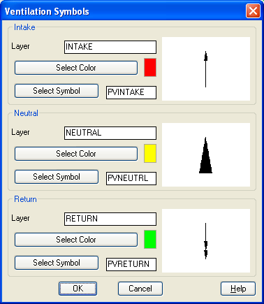
Stoppings:
To generate stoppings while generating projections and ventilation,
turn on the [x] Draw toggle in the stoppings section and
enter the headings where they should appear. The program can handle
up to three rows of stoppings for split ventilation systems.
Row1-3: These edit fields are used to indicate the heading in which the stopping will be placed. Since stoppings are normally placed halfway between headings, the valid input will usually have a decimal value of (.5). For example, as shown above, if a row of stoppings is to be placed between the 4th and 5th entries, the valid input is 4.5. To exclude a row, set the value to 0.0.
The block inserted can be modified, and is stored as PVSTOPPIN.dwg in the SCAD\SUP subdirectory.
Mandoors:
Mandoors can be automatically added to stoppings. Turn on the
[x] Draw toggle in the mandoor section and specify the
additional parameters below.
Angle: Indicates the rotation angle of the door symbol when placed on the stopping. The default value of 0 should provide the desired results in most cases, but can be changed if needed.
Space: Indicates the distance between doors along the row of stoppings. Usually set to 300 or 500 feet, however any numerical value is acceptable. The program will tract the running distance and automatically choose the correct break to place the mandoor in.
Break1: Indicates the break, relative to the Base Point, that the first mandoor should fall into. The program will begin tracking the space (described above), and place additional doors at the designated distance from this first break.
The block inserted can be modified, and is stored as PVMANDOR.dwg in the SCAD\SUP subdirectory.
Escapeways:
You can optionally place sets of escapeway symbols. Turn on the
[x] Draw toggle in the escapeway section and specify the
additional parameters below.
Prime: Indicates the entry number for the primary escapeway. The block is stored as PVESCPRI.dwg. Valid input would be a whole number with no decimal places.
Second: Indicates the entry number for the secondary escapeway. The block is stored as PVESCSEC.dwg. Valid input would be a whole number with no decimal places.
Offset: Indicates the distance to measure back from the row of ventilation symbols for the placement location of the escapeway symbol. Valid input would be a whole number with no decimal places.
The blocks inserted can be modified, and are stored in the SCAD\SUP subdirectory.
Layer Control:
Projections/Ventilation always generates the different sections of
its geometry (projection lines, pillars, ventilation arrows,
stoppings, mandoors, escapeway, and beltline) on separate layers.
These layers can be easily changed within the layer dialog and are
automatically saved when the specifications are saved. The layers
used are self-explanatory and are shown below.
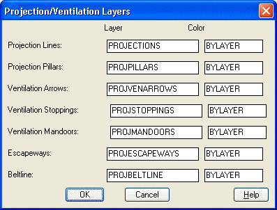
LAYER CONTROL SUB-DIALOG
To access the layer control dialog shown, press the layer button on the main dialog. After making changes to the layers, choose the OK button. If you wish to reject the changes made to the layer names, simply press the Cancel button.
Specification Save:
Projections/Ventilation can store all specifications previously
discussed to a file for later recall. To save a set of
specifications, choose the Save button from the main dialog. When
pressed, a standard file dialog will appear (defaulting to drawing
name) allowing you to save the *.PVS file. PVS stands for
Projections/Ventilation specification file. When chosen, the
default drawing filename will usually be the filename used for the
PVS file. Accept this name or enter a new one, changing directories
if appropriate. The normal scheme is to have one PVS file per
drawing, having the same name as the drawing and stored in the same
directory.
Specification Load:
Projections/Ventilation can re-load all specifications previously
discussed to a file for later recall. To load a set of
specifications, choose the Load button from the main dialog. When
pressed, a standard file dialog will appear, allowing you to enter
the *.PVS file. The default drawing filename will usually be the
filename used for the PVS file. Accept this name or enter a new
one, changing directories if appropriate.
Pulldown Menu Location: Works
Keyboard Command: panel3
Prerequisite: None