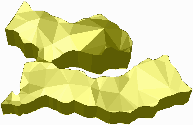
 3D view of
solid model
3D view of
solid modelThis command creates a solid model using TIN surfaces for the
roof and floor plus 3D perimeter polylines. This method for
creating a solid model applies when there are survey points on the
roof, floor and walls.
The TIN surfaces can be prepared with routines like Triangulate
& Contour in the Civil module. In Triangulate & Contour to
build the roof surface, turn on the option to Write Triangulation
File and select the roof points. Then repeat Triangulate &
Contour to build the floor surface by selecting the floor
points.
The 3D perimeter polylines represent the walls of the solid and
should have elevations between the floor and roof. If there are
survey points on the walls, these can be connected into 3D
polylines by using commands like Draw 3D Polyline. Multiple 3D
polylines can be used to create the solid model. 3D polylines that
are inside other 3D polylines are used as exclusion areas for the
solid model and create holes in the model.
To build the solid model, the program connects the 3D polylines
to the roof and floor surfaces.
 3D view of
solid model
3D view of
solid modelTop Surface To Read Select TIN file
Bottom Surface To Read Select TIN file
Select rib polylines.
Select objects: pick 3d polyline(s)
Solid File To Write Select MDL file
This example uses survey point data to build the solid by
creating the rib 3D polyline and top and bottom
surfaces.
From a new drawing, run Points > Set
Coordinate File and select a coordinate file named
sample_solid.crd from the Carlson Projects folder.
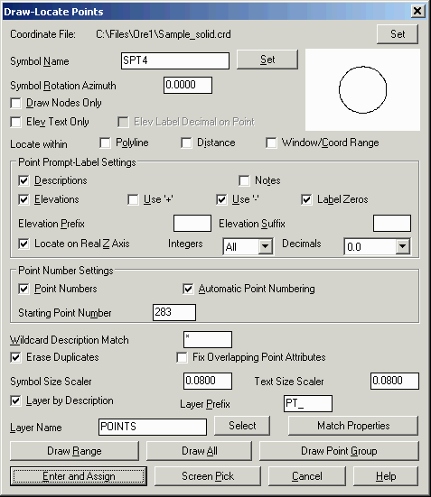
To have the points drawn at a good size, run Settings >
Drawing Setup and set the Horizontal Scale to 10 and the units
to English.
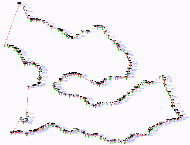
Next run Points > Draw/Locate Points and turn on the option
to Layer By Description and then pick Draw All. In this example,
the points have different description codes to identify roof, floor
and rib points.
 Step 2: Draw Rib 3D Perimeter
Polyline
Step 2: Draw Rib 3D Perimeter
Polyline
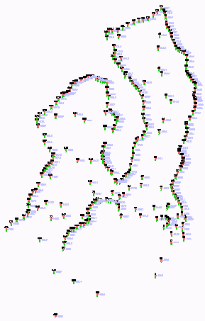
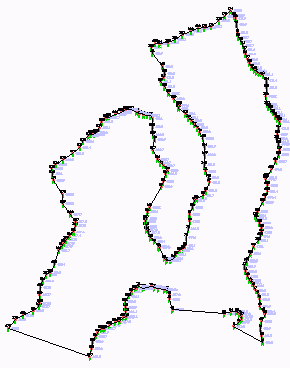
There are two codes of "R" and "P" for points on the perimeter.
To view only the perimeter points, run View > Isolate
Layers and pick on a point with a "R" description and a point
with a "P" description.
Next run Draw > Polyline > Polyline By Nearest
Found. Set the type to 3D Polyline, the max separation to 5 and
the layer to RIB_PERIM.

Then choose the Screen selection mode and then select all the
points.
Select point from screen or by point number
[<Screen>/Number]? press Enter
Select points.
Select objects:
all
The Polyline By Nearest Found connected the points except for
the large gaps. To create a single closed polyline and span these
gaps, run Edit > Join Nearest. Set the max separation to 100 and
the method as Directly Connect Endpoints.
 Then select all the polylines to be
connected.
Then select all the polylines to be
connected.
Select lines, arcs and unclosed polylines to
join.
Select objects: all
 Step 3: Draw Top and Bottom
Perimeter Polylines
Step 3: Draw Top and Bottom
Perimeter Polylines
To use for building the top and bottom surfaces, the next step
is to create top and bottom 3D perimeter polylines. First, turn all
the points back on by running View > Restore
Layers.
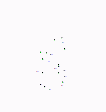
The bottom points have a description of "S". Run View >
Isolate Layers and pick on a "S" point.
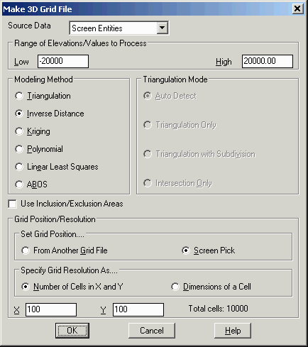
To elevate the perimeter polyline at the bottom surface, a grid
file is a good way to extrapolate the bottom points to cover the
perimeter. Run the Surface > Make 3D Grid File command
from the Civil module. Set the file name as bottom.grd. In the
options dialog, set the method as Inverse Distance and the grid
position as Screen Pick.
 For the grid
corners, pick a large window around the points to generously make
an area large enough to cover the perimeter.
For the grid
corners, pick a large window around the points to generously make
an area large enough to cover the perimeter.
Pick first grid corner: pick the lower left point
Pick opposite grid corner: pick the upper right
point
Select points, lines, polylines and faces to grid
from.
Select objects: all
Reading points ... 29
Use inverse distance to
which power [First/<Second>/Third/Other]? press
Enter
Use elliptical inverse distance [Yes/<No>]? press
Enter
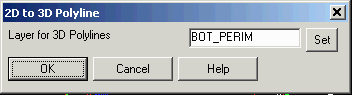
 Now that we have this bottom
surface, we can create a bottom 3D perimeter polyline. Turn on all
the layers again by running View > Restore Layers. Then
run 3D Data > 2D to 3D Polyline > By Surface Model
from the Civil model. Choose the bottom.grd as the surface to
process. Pick the rib polyline as the polylines to convert. Be sure
to answer YES to the Keep Existing Polyline prompt. Set the layer
to BOT_PERIM.
Now that we have this bottom
surface, we can create a bottom 3D perimeter polyline. Turn on all
the layers again by running View > Restore Layers. Then
run 3D Data > 2D to 3D Polyline > By Surface Model
from the Civil model. Choose the bottom.grd as the surface to
process. Pick the rib polyline as the polylines to convert. Be sure
to answer YES to the Keep Existing Polyline prompt. Set the layer
to BOT_PERIM.
Select polylines to convert.
Select
objects: pick the rib polyline
Use current polyline elevations as vertical offset from surface
[Yes/<No>]? press Enter
Keep existing polylines [Yes/<No>]? Y
The data is prepared and now the surfaces can be created. Let's
build the bottom surface first. Since the perimeter polyline for
rib, top and bottom are on top of each other, it is tricky to
select them individually. Run View > Layer Control and freeze
the layers for RIB_PERIM and TOP_PERIM. Then run View > Isolate
Layers and pick on a "S" point and the bottom perimeter
polyline.
 Next run
Surface > Triangulate & Contour. On the Triangulate tab,
turn on Write Triangulation File and set the file to bottom.tin.
Also, turn on Use Inclusion/Exclusion Areas. On the Contour tab,
turn off Draw Contours.
Next run
Surface > Triangulate & Contour. On the Triangulate tab,
turn on Write Triangulation File and set the file to bottom.tin.
Also, turn on Use Inclusion/Exclusion Areas. On the Contour tab,
turn off Draw Contours.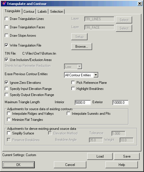 Pick OK on the dialog. Then select
the perimeter polyline for the Inclusion perimeter. For the
Exclusion perimeter prompt, press Enter for none. Then for the
select points prompt, type ALL.
Pick OK on the dialog. Then select
the perimeter polyline for the Inclusion perimeter. For the
Exclusion perimeter prompt, press Enter for none. Then for the
select points prompt, type ALL.We need to view the rib perimeter polyline for creating the
solid. Run View > Layer Control to thaw the RIB_PERIM
layer and freeze the TOP_PERIM and BOT_PERIM layers.
Finally, run Solid > Make Solid From Surfaces. Select
the top and bottom surfaces created in step 4 and the rib polyline
created in step 2. Then specify the solid model file name to
create.
Top Surface To Read Select TOP.TIN file
Bottom Surface To Read Select BOTTOM.TIN file
Select rib polylines.
Select objects: pick rib polyline
Solid File To Write Enter a file name
Pulldown Menu Location: Solid
Keyboard Command: make_solid
Prerequisite: 3d perimeter polyline and two surface
files