Lesson 20: CADnet PDF Section Import
This lesson imports cross sections from a PDF into Carlson .SCT
format. PDF files can contain different types of data. Some PDF's
contain linework vectors and others have images. For linework data,
the program brings the linework into the drawing. For images, the
program can either insert the image into the drawing or run a
raster-to-vector conversion process to create linework in the
drawing. In this first example, the PDF file contains
linework.
Import PDF File
To begin, run the Import PDF File command under the PDF menu in
CADnet. For details on import setup, see the Import PDF File
portion of this manual. The program starts by selecting the PDF
file to import. Then there is an options dialog. Turn on the Use
Colors, Join Nearest and Reduce Vertices options as shown. Then
pick Insert Linework.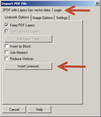
Then the program reads the PDF file to determine the number of
pages and let's you select the range to import.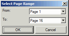
Next, the program prompts for a point to place the linework from
the PDF into the drawing. Pick a point in a blank area of the
drawing. Then enter the rotation angle. In this case, enter 90 for
the rotation. Finally, enter the scale. At this point, we don't
know the scale. So enter 1 and we will scale later.
Pick point to insert
PDF: pick a
point
Specify rotation angle
<0.0>: 90
Specify scale <1.0>:
press Enter
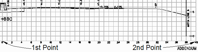
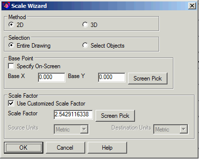
Scale Drawing
The next step is to scale the drawing to match the scale of the
section sheets. From the Edit menu, choose 2D Scale. Use the Screen
Pick option to set the scale factor. This routine prompts to pick
two points from the drawing and then enter the correct distance
between these two points. Pick two points with a known distance
such as two points on the section grid. It's best to pick two
points that are far apart to reduce errors with screen picking
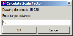
precision. For this example, pick at offset 0 and at offset 40 on
the section grid as shown. Enter the target distance of
40.
Join Section Lines
In this example, the section lines for the existing and design
surfaces have a gap at the center median. In order to have sections
for both the left and right sides of the road, these separate
section lines need to be connected. Run the Join Nearest command
from the Edit menu. Set the max separation to 5 to have enough to
span the gap. Fill out the rest of the options as shown. Then pick
the existing and design section lines on the left and right
sides.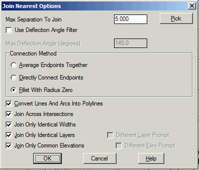

Create Section Files in Carlson Construction or Carlson
Civil
Now that the drawing has the section lines, which to Carlson
Construction or Carlson Civil. Next, run Create Sections from
Polylines on Section Grids. In the options dialog, set the
horizontal and vertical scales to match the section grid. The ratio
between horizontal and vertical scales is used to determine the
vertical exaggeration. Set the .sct file name for the first section
for the existing ground. Turn on the option to create a second
section and set the file name for the design surface. Then pick
OK.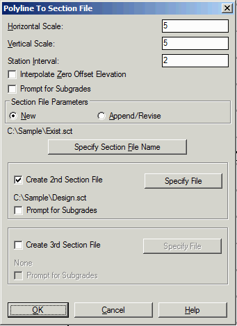 The program then prompts for the
station to create and the grid elevation. Then pick the section
grid point at the zero offset and that elevation. Then pick the
existing and design surfaces. Repeat this input for the other
stations.
The program then prompts for the
station to create and the grid elevation. Then pick the section
grid point at the zero offset and that elevation. Then pick the
existing and design surfaces. Repeat this input for the other
stations.
Exit/Pick text/<Station
<0.00>>: 1880
Exit/Pick text/<Starting
elevation of grid <100.00>>: 0
Pick point at starting elevation
and zero offset of section ([Enter] for none): pick the section grid for station 1+880 at
offset 0 and elevation 0
Select station 1880.00 1st section
polyline: pick the
existing ground line
Select station 1880.00 2nd section
polyline: pick the design
surface line
Exit/Pick text/<Station
<1882.00>>: 1900
Exit/Pick text/<Starting
elevation of grid <0.00>>: 5
Pick point at starting elevation
and zero offset of section ([Enter] for none): pick the section grid for station 1+900 at
offset 0 and elevation 5
Select station 1900.00 1st section
polyline: pick the
existing ground line
Select station 1900.00 2nd section
polyline: pick the design
surface line
Exit/Pick text/<Station
<1902.00>>: E for
exit
Verify Section Data
There are several ways to verify the section data. Use Draw Section
File to plot the sections and compare to the original PDF. Use
Section Report to print out the station, offset and elevation
section data. Use Input-Edit Section File to show a graphic preview
of the sections along with a spreadsheet of the values. The dialog
here shows the Input-Edit Section file screen for both the existing
and design surfaces.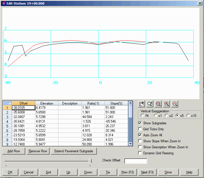
Use the command Calculate Section Volumes to report end-area
volumes between two section files.