Tool 7 - 3D Polyline by Slope on Surface
Tool 8 - 2D to 3D Polyline by Surface Model
Tool 10 - Profile to 3D Polyline
1 Click the desktop icon for Carlson and start-up Carlson Software.
2 Once in Carlson, exit out of the Startup Wizard (if it appears) and click Open under the File pulldown menu. Look for the file example2.dwg drawing in the "\Carlson Projects" folder and open it.
3
Since example2.dwg will also be used multiple
times throughout this tutorial, you might want to make a copy so
that you don't overwrite the initial drawing. Click Save
As in the File menu and choose a different name, such as
example2a.dwg.
4 Load the Civil Module
by running Settings->Carlson Menus->Civil Menu.
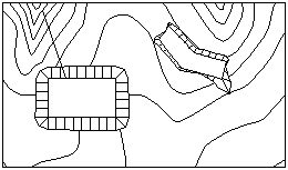
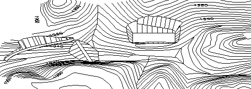
The most basic use of a polyline is for the creation of flat-bottomed pits and flat "building pads" at any desired elevation. See the two polyline examples shown here.
|
|
|
The rectangle was carved out of the map by first doing the Rectang command, and making a rectangular polyline in the SW corner of the map as shown above. Then we did Erase by Closed Polyline, under the Edit pulldown, selecting the rectangular perimeter and checking Erase Outside. The two polylines are drawn by the Rectang command for the pit, and the PL command at an elevation of 0.00 for the pad as shown above (make sure to use the 'Close' option for the final line).
Then, we selected Design Pad Template, found in the Surface pulldown menu. Make sure Source of Target Surface Model is set to Screen Entities and pick OK. We began with the rectangular pit.
Pick Lower Left limit of pad
disturbed area: pick the
lower left of map
Pick Upper Right limit of pad
disturbed area: pick the
upper right of entire map
A dialog box appears. Click OK to accept defaults.
Pick the pad polyline:
pick the rectangular
pit
Enter the fill outslope ratio
<2.00>: 1
Enter the cut outslope ratio
<1.00>: 1
Enter the pad elevation:
1960 (Elevation of the
pit)
Calculate earthwork volumes
[<Yes>/No]? press
Enter
Review the report, and then Exit from it.
Adjust parameters and redesign pad
[Yes/<No>]? press
Enter Write final surface
to grid file [Yes/<No>]? press Enter
Trim existing contours inside pad
perimeter [Yes/<No>]? Y
Retain trimmed polyline segments
[Yes/<No>]? press
Enter
Contour the pad
[<Yes>/No]? N
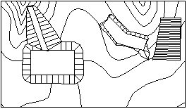
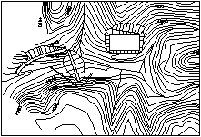
We then repeated the above steps for the pad on the right, except this time, we entered 1964 for the pad elevation. The results are shown below, in 2D and 3D views.

|

|
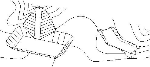
This is an obvious tool for creating terrains. Before drawing the polyline, try Viewpoint 3D under the View pulldown, and choose a SW viewing angle at 35 degrees above the XY plane to get a view similar to the 3D graphic shown above. In this view, erase the original pad base polyline, which is still at an elevation of 0.00. This will prevent the "nea" snap from finding the 0 elevation base polyline instead of the new, green, pad polyline. Enter Plan at the command prompt, followed by two Enters, to go back to Plan View. Now, we want to draw the polyline as shown below. We recommend the use of Carlson's 3D Polyline, found near the top of the Draw pulldown menu. We want to build a ramp from north to south into the pit. We will "arbitrarily" start at elevation 1978 by "snapping" to the 1978 contour with the "nea" snap (nearest), and then snap to the base of the pit at 1950 with the nearest snap. In the following steps, we will offset this 3D Polyline, connect its ends by Join Nearest, and create a pad template with 2:1 side slopes.
|

|
After the 3D Polyline is drawn, do the Inquiry command Angle & Distance, Linework option, to check the percent slope of the 3D polyline. At approximately 10% grade, it should be "drivable" by haul trucks. Now, use the Edit > Copy > Standard Copy command and make a copy of the polyline, placing it to the right. You will want to use the Polar Tracking to ensure that the second 3D Polyline also contacts the base of pit.
Now find Join Nearest under the Edit pulldown menu. Select Directly Connect Endpoints, and enter a 35 offset tolerance. Pick both 3D polylines to join them, as shown in the graphic.
Now we have a 3D polyline closed perimeter, which can act as a pad. It is advisable to first do a List command, under Inquiry, to verify that each pad vertex is non-zero. Now, pick the Design Pad Template routine under the Surface menu. We will no longer be asked for a pad elevation, since the program will obtain the variable pad elevation from the vertices of the 3D polyline. Accept the default settings, and pick a window that encompasses the whole pad.
Enter the fill outslope ratio
<2.00>: press
Enter
Enter the cut outslope ratio
<2.00>: press
Enter
Calculate earthwork volumes
[<Yes>/No]? press
Enter
Review the report, and then Exit from it.
Adjust parameters and redesign pad
[Yes/<No>]? press
Enter
Write final surface to grid file
[Yes/<No>]? press
Enter
Trim existing contours inside pad
perimeter [Yes/<No>]? Y
Reading the selection set
...
Retain trimmed polyline segments [Yes/<No>]?
press Enter
Contour the pad
[<Yes>/No]? N
The 2:1 cut side slopes (fill side slope is irrelevant, since we are in cut) leads to the drawing shown in the graphic.
Note that we are consistently using Design Pad Template to trim existing contours and 3D polylines, and to not retain the trimmed portion. We are also consistently selecting not to draw contours. In this manner, we iterate our way to the desired final terrain. We should also note that we are using the standard 50x50 "number" of cells in the Pad Template routine, windowing the entire site each time. More cells or smaller dimensioned cells lead to a finer calculation.
Design Pad Template in the Surface pull-down menu also works with a 2D or 3D polyline that is open and not closed. In this case, the routine will ask for which side to offset (with a closed polyline, it always offsets outward). For example, suppose you were concerned where a pit located along the northeast side of the site would "catch" if it sloped at 2:1 from an elevation varying from 1980 at the north end to 1985 at the south end. To put this 3D Polyline in, select 3D Polyline under the Draw pulldown menu, and choose the prompt for elevation option. Enter the north elevation as 1980 and the south elevation as 1985. Then do Design Pad Template and choose the left side for the offset at 10:1.
|
|
The top of the cut did not impact the building pad or the parking lot.
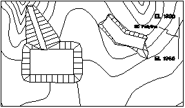
Here we have drawn a closed polyline in the lower right of the drawing, and will set its elevation to the lowest elevation the line crosses (as prompted by the program). This will ensure that the pond is fully incised and does not have any fill slopes. The Design Bench Pond routine is found under the Surface pulldown menu (make sure that you are working in the Civil Menu). It is based on the use of the closed polyline representing the top of the pond. The program cuts a circular pond into the existing terrain.
Unlike Design Pad Template, the Design Bench Pond routine works "inward". The main thing to remember is that if you have roughly 20 feet to the center of the pond, and you want to go downward at 2:1, do not ask for a depth greater than 10 feet. This will cause one side to pass beyond the other, and you will "hourglass" the interior. Another concept to remember is that the program will cut downward from the drawn polyline, which is placed at an elevation representing the water level or top of pond. A separate cut and fill ratio can be applied to the outside of the drawn polyline. If you place the pond fully in cut (fully incised), then one cut ratio would apply to the interior going down to the base of pond, and another would apply to the exterior going up to "daylight". Of course, the same ratio can be entered for both slopes.

|

|
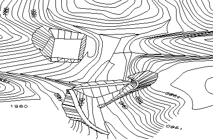
A typical farm pond might have the downhill side in fill and the uphill side in cut. In fill, the flat-topped "bench" might be 10 feet. In cut, the bench would disappear. Cut above water into original ground might be 6:1. Cut below water might be 3:1. Fill could be set at 6:1 and 3:1 below water. In this case, we would remove the top bench in cut. The graphic shown here is a bench pond cut into the top center of the drawing at elevation 1994.
If you are getting the idea, try this on your own:
Draw a 3D Polyline that will drain the lower right pond into the upper left pond. Do this through use of the 3D Polyline command, under Draw. Issue the command, and use a "nea" snap maybe one-third down the northwest "slope direction line" in the pond at the lower right of the graphic. Connect using a "nea" snap to a point halfway down the southeast running "slope direction line" in the pond at the upper left of the graphic.
List your 3D polyline to be sure it runs downhill from approximately 1992 to 1989, or thereabouts. We're only after the concept here. Then do Offset 3D Polyline four feet either way for base of ditch. Connect the ends up with Join Nearest, tolerating 5' separation. Then do Design Pad Template at 3:1 side slopes in Cut and Fill. Your result is shown in 3D.
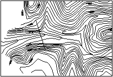
To begin this exercise, reopen the original example2.dwg file. We can "carve out" another portion of our base map by first drawing a "Rectang" in the SW corner of the map as shown below. Then choose Erase by Closed Polyline, under the Edit pulldown, selecting the rectangular perimeter and checking Erase Outside. If you'd like, you can freeze the BORDER layer to clean up your drawing. To preserve the original example2.dwg file, do a Save As under a new filename, such as valley1.dwg.
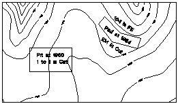
Unlike Design Bench Pond, the Design Valley Pond routine requires only a polyline axis line for the center of the dam. The polyline can be a 2-point polyline, or it can have several vertices along its length to create a concave or convex dam structure. The main thing is to "overdraw" the axis polyline, make it ride up on the left and right hillside, well beyond the desired top of dam elevation. This allows the routine to look inward and find the extents of the dam on each hillside, without doing an artificial extension of the polyline. Just "overdo" the length of the axis line and you are in business.
Another aspect to concentrate on is the desirability to select enough terrain upstream to enable the program to compute the full waterline extents - the limits of the dammed-up water. Without enough upstream terrain in the initial selection set (which acts like a crossing selection), you will not be able to compute the limits of the water surface and the pond stage-storage information.
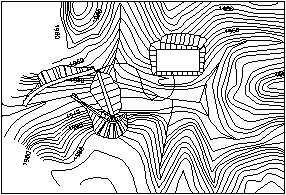
Our axis polyline runs from approximately 1960 on one side of the valley to 1960 on the other. It crosses the valley at 1931. Let's decide to put the top of dam at 1950 even. We will make the dam 20' wide, with 3:1 downstream and 4:1 upstream slopes. Select Design Valley Pond under Surface > Design Pond. Source of surface model is, as always in this case study, the screen, so create a window around our new polyline, then click somewhere within where the pond will be. Respond to the prompts as shown below.

|
|
Source of surface model
[File/<Screen>]? press Enter
Pick Lower Left limit of pond
disturbed area: pick the
lower left location of the valley pond region
Pick Upper Right limit of pond
disturbed area: pick the
upper right location of the valley pond region
Pick the top of pond
polyline: pick the
polyline that represent the centerline of the dam
Enter slopes as percent grade or
slope ratio [Percent/<Ratio>]? press Enter
Enter the outslope ratio
<2.00>: 4
Enter the interior slope ratio
<4.00>: 3
Enter the top of dam width
<10.0>: 20
Enter the top of dam
elevation: 1950
Side Polyline Spacing
<10.0>: press
Enter
Cut pond interior
[Yes/<No>]? press
Enter
Calculate stage-storage values
[<Yes>/No]? N
Output grid file of final pond
surface [Yes/<No>]? press Enter
Adjust parameters and redesign
pond [Yes/<No>]? press Enter
Trim existing contours inside pond
perimeter [Yes/<No>]? Y
Retain trimmed polyline segments
[Yes/<No>]? press
Enter
Contour the pond
[<Yes>/No]? N
How would you start at the top of dam (elevation 1950) and build a road running downhill at 6% grade? Or, in general, how would you obtain 3D polylines for roads and diversion ditches that follow the terrain at prescribed grades starting at desired points?
The answer is 3D Polyline by Slope on Surface (located under the 3D Data menu, within the 3D Polyline Utilities pulldown). This routine requires that we make a grid or triangulation file for the terrain. Use the command Make 3D Grid File under the Surface pulldown menu, and store the file as Dam.grd. Under Grid Position/Resolution, select Screen Pick and specify a 20x20 cell dimension. Draw a window that encompasses the entire drawing, and pick all points and lines. Then run the 3D Polyline by Slope on Surface command and answer the prompts as follows:
Enter the polyline layer
<SLOPE_PLINE>: press
Enter
Select Dam.grd as the grid file to use.
Limiting length for polyline
(Enter for none): press
Enter
Pick origin point of 3D
polyline: pick a starting
point on the north side of the dam
Direction of 3D polyline
[<Up>/Down]? D
Direction of 3D polyline facing
down slope [<Left>/Right]? R
Slope format
[<Percent>/Ratio/Degree]: press Enter
Enter design slope percent:
6
Pick origin point of 3D polyline
(Enter to end): press
Enter

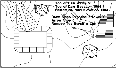
After the new 3D polyline is drawn, offset it into the hill with the Offset 3D Polyline command (under 3D Data > 3D Polyline Utilities). Press Enter for the defaults when prompted, but make sure to use a horizontal offset of 20, and a vertical offset of 0 to define the road. Then join the ends with Join Nearest, and you should obtain the drawing shown here.

Now we want to use Design Pad Template to carve our road into the terrain. In the drawing showing text information at the upper left, we can see that we now have a "pad" for pad template. Because the southern side of the pad follows close to the original ground, it may "cantilever" over into the "air" in a few places based on the resolution of the calculation. It is recommended that the fill ratio used to catch the ground be low, such as 1:1 rather than 2:1, so that short cantilevered sections of the pad, if placed on natural 2:1 terrain, don't "skim" over the ground and create unnecessary fill. For the cut sections, we will use 3:1 to carve the road into the solid hillside. The result can be seen in 3D.

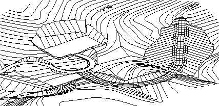
The 3D view above reveals a 3D polyline running up the base of the stream channel in which the pond was built. Such 3D polylines are important in modeling accurate surfaces for pond design, pad templates and volumes in general. For example, if you were to triangulate and contour the valley at 1' interval (currently the contours are at 4' interval), you would obtain poor valley contours which "square off" in the valley - if you did not select the 3D Polyline "break line".
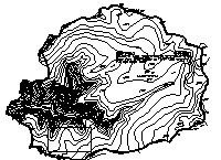
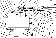
Thus, an important strategy, better yet policy, is to dress up raw contour maps with valley and ridgeline 3D polylines that act as break lines, and restore the true character of the terrain. The best way to make these 3D polylines is to draw 2D polylines in drains and ridges (see the three circled examples) and "drape" them on the terrain. This is done using the 2D to 3D Polyline by Surface Model command, found under the 3D Data pulldown menu. You can use the Dam.grd file that you created earlier.

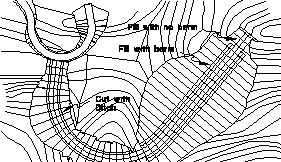
More than a command to "dress up" contour maps for greater modeling accuracy, the 2D to 3D Polyline by Surface Model command (sometimes called the "drape" command) has unexpected uses. In the example, a strata angling along a pit face creates instability in the upper part of the pit. The goal is to "lay back" the pit at 2:1 above the strata demarcation line, and retain the 1:1 slope below that line (which is drawn as a 2D polyline at the outset, then converted to 3D when draped).
|
|
After the 3D Polyline is "draped" on the surface, you should use Change > Elevations under the Edit menu to drop the entire 3D Polyline just a little, such as -0.2. This will ensure it is fully in Cut. Then the Design Pad Template command can be used to perform a one-sided offset at 2:1 in Cut, resulting in the drawing, shown here in 3D view.
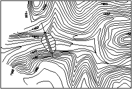
Out next goal is to build a diversion ditch around the dam using Input-Edit Profile. With Osnaps turned off, draw a simple 2D polyline ("PL" command or Carlson's "2DP") that starts on the water side of the valley dam, near the "break line" that was drawn earlier, and curves around the hill to the south and into the drainage below the dam, as shown in the graphic. The syntax for this using the PL command is: pick first point, pick second point to get a tangent (straight section) going, then type A for arc, arc it around the dam, then do L for line and a second L for length, and pick a point that comes off tangent from the arc and ends in the stream bed below the dam. Then press Enter to exit the PL command.

Now we are going to make this 2D polyline a 3D polyline with a prescribed profile. To prepare for this, we do Polyline Info under the Inquiry pulldown menu, and write down the length of the polyline (this will become the length of the profile we enter). This one here is 377.6 feet, which we will round up to 378. We then use List Elevation under the Inquiry pulldown menu, and pick on the 3D "break line" polyline as close as we can to the point where our 2D polyline makes contact. In our example, that elevation is reported as 1929.4 (along with all vertices elevations). We determine ahead of time that we want the first 50 feet of the diversion ditch to be a 1% downhill slope, starting at elevation 1946 (allowing 4 feet of freeboard to the top of the dam at 1950). We are ready for Input-Edit Profile File in the Profiles menu. Call it Ditch.pro, and fill out the profile dialog as shown in the graphic, but with the data that applies to your example.

The order of entry might be 0 and 1946 on the first line, 378 and 1929.4 on the third line, and 50 and slope% of -1 on the second line, completing the profile. Save it, and Quit from the dialog. The one remaining step to get a 3D polyline is to select the command Profile to 3D Polyline under the Profiles pulldown menu. Pick the ditch centerline and apply the newly saved profile to it. Erase the old centerline and you obtain a "yellow" colored 3D polyline centerline.
Use the command Offset 3D Polyline to offset the ditch into the hill 8 feet for an 8' base (or offset 4' either way and erase the original centerline). In either case, you have two parallel 3D polylines. Now, do Join Nearest, tolerate 9' of separation and Directly Connect Endpoints within Join Nearest.
Note how 3D Polyline > Offset 3D Polyline and Join Nearest become a familiar sequence in doing pad template work! Now create a Design Pad Template with a cut slope of 1.5 to 1.
|

|
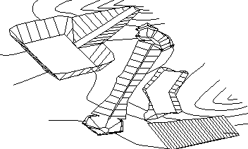
If it is apparent that the diversion ditch was initially drawn too far into the pond area and created fill, as seen in the graphic, then there is the option to re-design or simply to trim off the fill portion. This likewise applies to the portion of the diversion ditch at its terminus downstream. Note that gaps in contours that need to be re-closed can be very quickly fixed with Join Nearest. With the trimming completed, the final design appears in 3D.
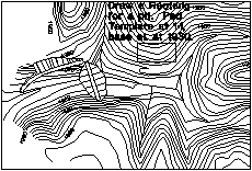
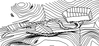
Our next topic of discussion will focus on building a curving road from the top of dam to the base of pit using Input-Edit Profile and converting that profile to a 3D Polyline. Looking at the 3D view in the graphic, let's extend the road from the top of dam into the base of the pit, following a uniform grade and entering the pit at right angles on the south side (or right-side, as seen in the graphic). This "word problem" is nothing more than another iteration of Input-Edit Profile File and Profile to 3D Polyline. The first challenge is to draw the 2D polyline using the PL command. We've already learned how to do this and use the second L approach to come off tangent from an arc. We end up with a centerline that might look like the one in the graphic.
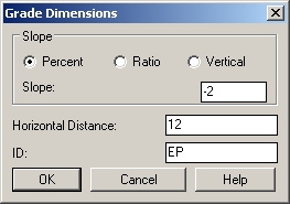
Just as before, find the length of the polyline using Polyline Info under the Inquiry menu. We know the profile... it runs from 1950 (the top of dam) down to 1930 in the base of pit. So we go straight to Input-Edit Profile File, perhaps name it Road (Road.pro) and put in a simple two-entry profile as shown in the dialog box display here.

The slope of the road at -3.17 percent is very acceptable for any type of vehicle. So now we choose Profile to 3D Polyline and apply Road.pro to the road centerline. This time we will offset the new 3D polyline 10 feet either side using 3D Polyline Offset, and erase the original middle centerline (or render it harmless for terrain modeling by the command 3D Entity to 2D found under the Edit menu).
This raises an important point: when we select entities from the screen using Design Pad Template, Design Valley Pond and Design Bench Pond, the pad or pond polyline itself is filtered out of the selection set, and it is not used for modeling the original surface.
If we left intact a 3D polyline centerline that was not part of our pad, it would skew the surface model badly. Thus, if we offset left and right for the outside of the road, the middle of the road must go, must be erased, unless we chose the "grid file" option for the original surface. After offsetting 10' either side and erasing the center 3D polyline, we Join Nearest at a 21' tolerance. Then we do Design Pad Template at standard 2:1 slopes.
Here is the final 3D view (you might use Design Pad Template to divert the ditch and not flood the pit!).
The limitation of Offset 3D Polyline within Pad Template is that roads cannot easily be given dynamic characteristics: They won't automatically carve in ditches in cut, or build a berm in fill where fill exceeds a certain threshold, for example.
Since these "intelligent" features exist within the Design Template routine in the Roads menu of the Civil Design module, all we need to do is invoke the "template" option within the Pad Template. Pad Template will then go out and get a Design Template and apply it to the one-sided or closed pad perimeter. To illustrate this, let's first make a centerline that will have cut and fill. Consider the centerline drawn in the graphic.
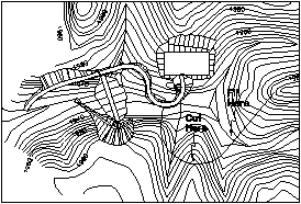
If we go a uniform grade from the existing road, upward to the ending elevation (which might represent a mining bench), we are "bound" to get cut as we cross the lower point and fill as we cross the second drain. To "guarantee" fill, we will go uphill early and lessen the last portion of the grade, using a vertical curve length of 500 between profile grades. This is another exercise of Polyline Info (for length), verifying start and end grades, and Input-Edit Profile (as shown in the dialog).
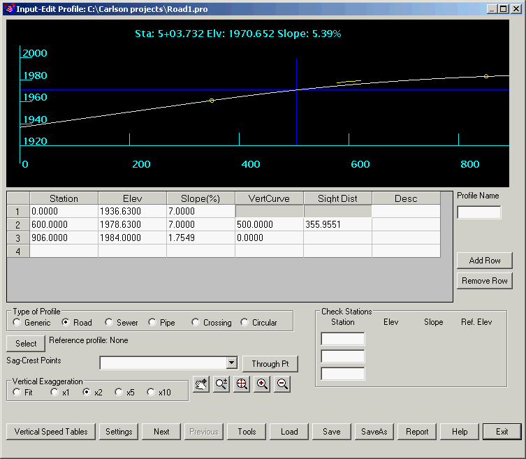
With the profile input (named road1.pro), we can select Profile to 3D Polyline and turn yet another 2D polyline into a 3D polyline. The difference now is that we will not offset the 3D polyline to create a closed, looping "pad". We will instead use a template made in Design Template, and apply it to the 3D polyline.
Design Template, located under the Roads menu in the Civil Design module, is icon driven. Create a new template, you may call it Roads1. See this horizontal strip of icon options.
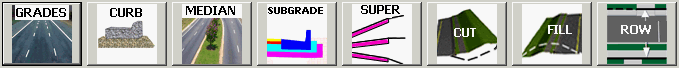
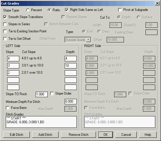
Shown here is a selection of dialogs that illustrate our entry of a 24' wide road (12' either side) at 2% slope, no shoulder, no subgrade, a 3:1 slope for 6' to the base of ditch, a conditional cut upslope, a 3:1 slope in fill, but a 2:1 berm in fill, rising 4 feet, used when fill exceeds 5 feet. To begin with, this small dialog appears when the Grades button, within the Design Template dialog box, is clicked.
Note that when you are putting in a ditch, you need to click "Add Ditch" at the lower-left of the Cut Grades dialog. The conditional cut upslopes mean 4:1 up to 4 feet of fill, 3:1 between 4 and 10 feet of fill and 2:1 above 10 feet of fill.
The Fill Grade dialog looks similar, with two entries for berms (Add Berm is selected twice), one for up slope at 2:1 for 8 feet (which translates to 4 feet vertically) and a second for downslope of 2:1 for 8 feet for the back of berm.

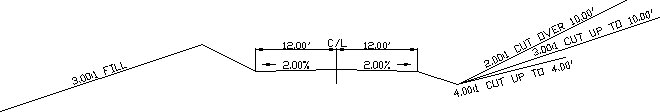
The "typical section" can be drawn using the command Draw Typical Template under Roads. This will help you verify the quality of your template. Our template is shown here.
Now let's use the Design Pad Template routine, found in the Surface menu. The dialog box for Design Pad Template is filled out as shown.
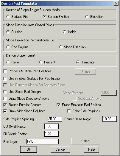
For the first time, we have selected the "template" option under Design Slope Format.
Finally, here is how the road appears in 3D using the View > Viewpoint 3D command.
This completes the Lesson 8 tutorial: A Dozen Tools for Surface Design.