r

Fill the dialogs in as shown, and press OK. Also look at the selection tab at the top and set settings as required or needed.
This is the easiest of the tutorials, and could be completed in as little as three minutes. If that is all the time you have, and you have purchased the Civil Design program, do this one first!
1 Click the desktop icon for Carlson and start-up Carlson Software.
2 Once in Carlson, start a new drawing (exit out of the Start Wizard if it appears) and go straight to the Points pulldown menu. Choose Set CooRDinate File. You will then be asked to choose the coordinate file that you want to use. Select Topo.crd as shown here, and click Open.

Now go to Draw-Locate Points under the Points pulldown menu. You obtain this dialog:
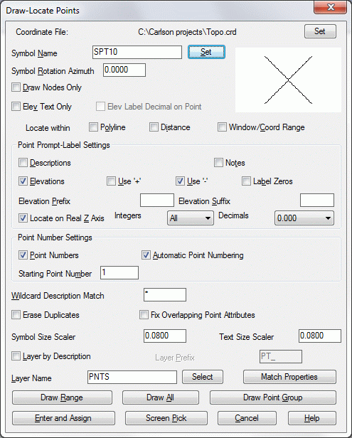
Choose Symbol 10 by clicking Select at the top of the dialog, then picking Symbol SPT10 from the options that appear. All other settings are default. Verify that you match what appears here. Then click the option Draw All.
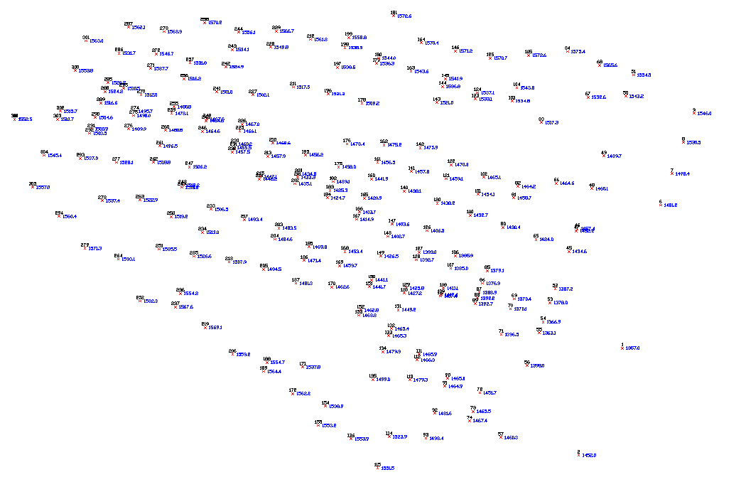
The points immediately plot on the screen, and the program zooms to the extents of the points. If you don't see the points, select Extents under View. The point plot is shown below:
3 Triangulate & Contour. Be sure you are in the Civil Design program (Pick Civil Menu under Settings > Carlson Menus). Under the Surface pulldown menu, pick Triangulate & Contour. The following dialog boxes will appear which you should fill out as shown. We'll start with the Contour tab.
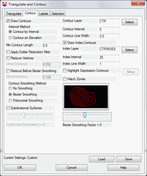
In the Contour tab, as shown above, set the contour interval to 5.0, turn on Draw Index Contours and set its interval to 25.0 (index intervals are most often 5 times the standard contour interval). The Contour tab should appear as shown above. Click on the Triangulate tab.

In the Labels tab, we want to label index contours only (so it's
not too busy) and do 2 internal labels per contour. This works very
well for a valley. It puts a contour label on each side of the
valley. Sometimes you may prefer to label a specific length of
contours
r
Fill the dialogs in as shown, and press OK. Also look at the
selection tab at the top and set settings as required or
needed.
Select the points and breaklines to
Triangulate.
Select objects: ALL (All means select
everything visible on the screen)
615 found
Select objects: press ENTER
(for no more)
The contours are drawn. Now, choose the command Freeze Layer under the View menu and pick on one of the points (its number or its elevation), and press Enter. The points freeze. Here is the plot so far:
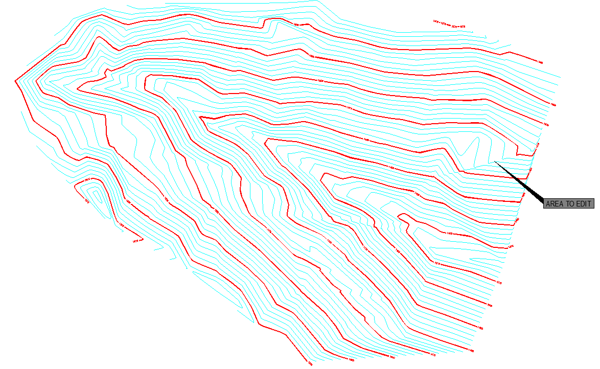
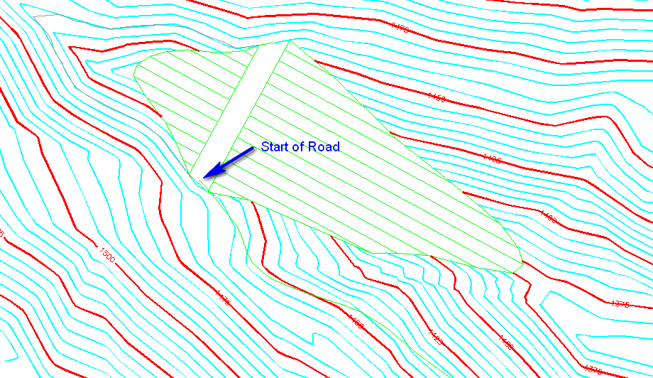
4 Edit Contours. The arrow above points to an area that needs editing. This area is enlarged below. You may want to zoom into this area for the next edit operation, and zoom back out when you are finished.
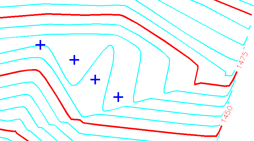
Choose the command Edit Contours. This is found by going to the Surface pulldown menu and choosing Contour Utilities.
Select contour to edit: click on the 1460 contour (leftmost cursor, shown
above)
Pick intermediate point (Enter to end):
click for the new position of the 1460
contour
Pick intermediate point ('U' to Undo,Enter to
end): click a 3rd time
Pick intermediate point ('U' to Undo,Enter to
end): click a 4th time (more if
desired you are re-drawing the contour, in effect)
Pick intermediate point ('U' to Undo,Enter to
end): press Enter before you
want to reconnect to the original 1460 as above
Pick reconnection point on contour:
pick on the 1460 contour to
reconnect
Select contour to edit: continue and edit other contours, as desired or press
Enter to end
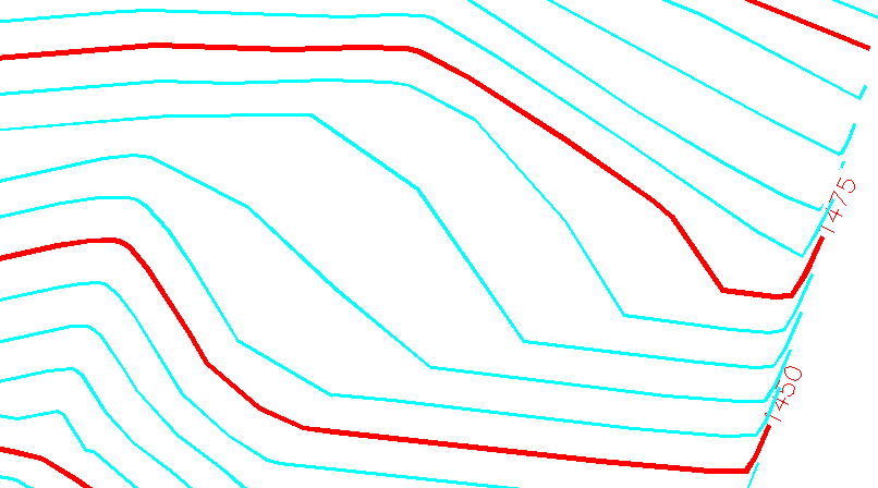
The Edit Contour command will keep every edited contour (e.g. our 1460 contour) as a single polyline. The edited segment is auto-joined to the before and after segments. Results below:
5 Draw a Polyline across the Valley to represent the Centerline of a dam. Choose the Draw pulldown menu and select 2D Polyline (near the top of the menu). Click the OK button on the Polyline 2D Options dialog box if it appears. This is an enhanced version of the standard polyline command which draws the same polyline entity that you get when you type PL at the command prompt. Try to split the valley with the polyline (see below).
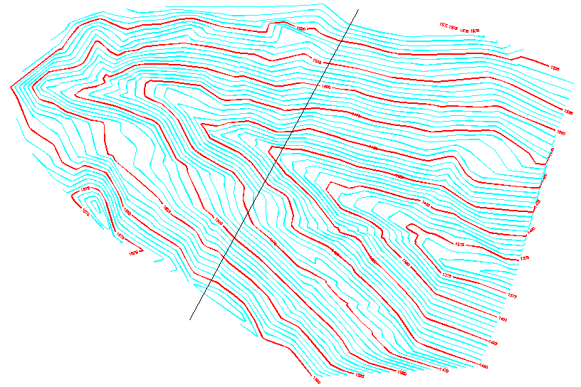
[Continue/Extend/Follow/Options/<Pick
point or point numbers>]: pick on
the left side of the valley
Segment length: 0.00, Total length: 0.00
[Arc/Close/Distance/Follow/Undo/<Pick point or point
numbers>]: pick on the right side
of the valley
Segment length: 608.27, Total length:
608.27
[Arc/Close/Distance/Extend/Follow/Line/Undo/<Pick point or point
numbers>]: press Enter (for
no more vertices)
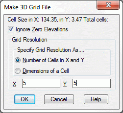
6 Making Grid Files. A grid file can be used for volumes, comparing one grid to another. While we have the original contours visible, we should save a Topo-e grid file (topo-existing). Select Make 3D Grid File under the Surface pulldown menu. Let's call the original ground grid Topo-e as shown in the dialog here.
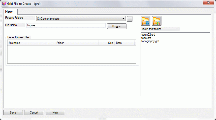
Click Save. This leads to another dialog:
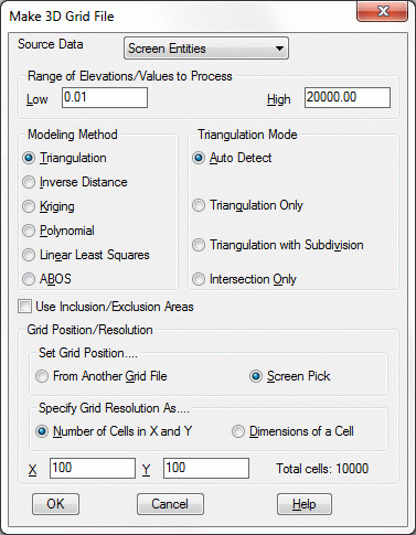
Use the settings shown in this above dialog box (plenty accurate for this application). Click OK.
Pick first grid corner: pick to the lower left of the topo area
Pick opposite grid corner: pick to the upper right of the topo area
Select points, lines, polylines and faces to
grid from.
Select objects: ALL (again we can use
the all selection)
Select objects: press Enter (for no more)
The file Topo-e.grd is then stored.
Tip: Whenever you make Carlson files, such as coordinate files (crd), grid files (grd), and even pond capacity files (cap), they store to disk. When you do an Undo command (U for undo), you undo the graphics, but the files are safely stored and are not undone. Carlson does not like to overdo making files. Make them if you want, but we will not make any that are not needed. The entire contouring process, above, was completed without making a single new file, for example, though there were options, clicked off by default, to make files.
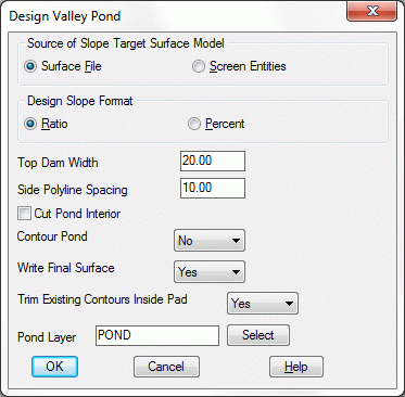
7 Design
Valley Pond. Select Design Valley
Pond which can be found under Surface > Design Pond.
Click OK. Pick the top of pond
polyline: pick the polyline as drawn
earlier
Select the grid file Topo-e.grd. Then click Open. If we had no grid
file, we could have chosen the screen-select option, and selected
all objects.
Pick a point within the pond:
pick upstream (northwesterly) of the
polyline
Enter the outslope ratio <2.0>:
3
Enter the interior slope ratio
<3.0>: 4
Range of existing elevations along dam top:
1421.43 to 1576.42
Enter the top of dam elevation: 1460
Calculate stage-storage values
[<Yes>/No]? y
Method to specify storage elevations
[<Automatic>/Interval/Manual]? press Enter
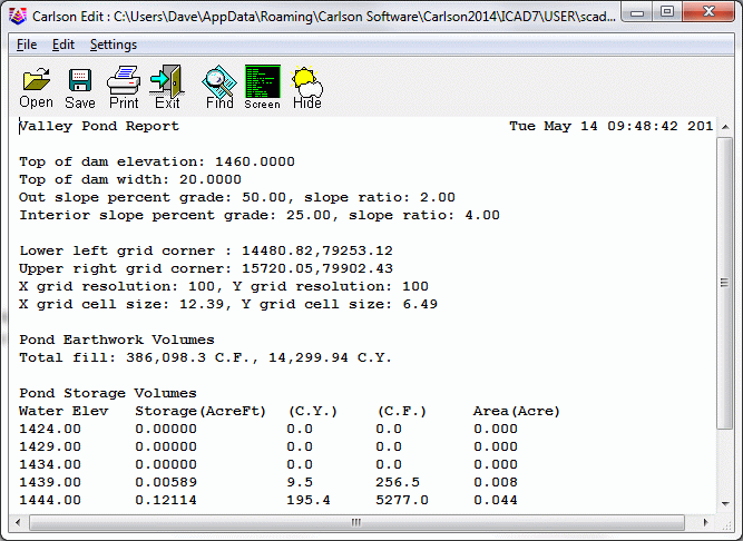
The following report includes earthwork volumes and water
storage volumes.(Your report will be slightly different)
Click the Exit icon to continue forward in the process.
Output grid file of final pond surface
[Yes/<No>]? Y
Save the surface, that includes the pond, in the file Topo-d for
Topo with dam.
Write stage-storage to file
[Yes/<No>]? Y
Save the pond stage-storage curve information to a file (choose any
name). Click Save.
Adjust parameters and redesign pond
[Yes/<No>]? N
Retain trimmed polyline segments
[Yes/<No>]? N
The process is complete. At the command line, enter E for erase and then when it says Select objects: pick on the centerline of the dam, then Enter for no more picks, and the centerline will erase.
Tips: The stage-storage curve that you save will plot in the Carlson Hydrology program. It makes a nice, handy plot for report purposes. See Lesson 11 - Hydrology and Watershed Analysis. Also, it's always good to save your drawing periodically.
8 Check it out in 3D. Select the 3D Viewer Window option, under the View pulldown.
Select all entities for the scene.
Select objects: ALL (again, we use the
all selection)
Select objects: press ENTER for no more
This leads to the starter view (a plan view) shown below:
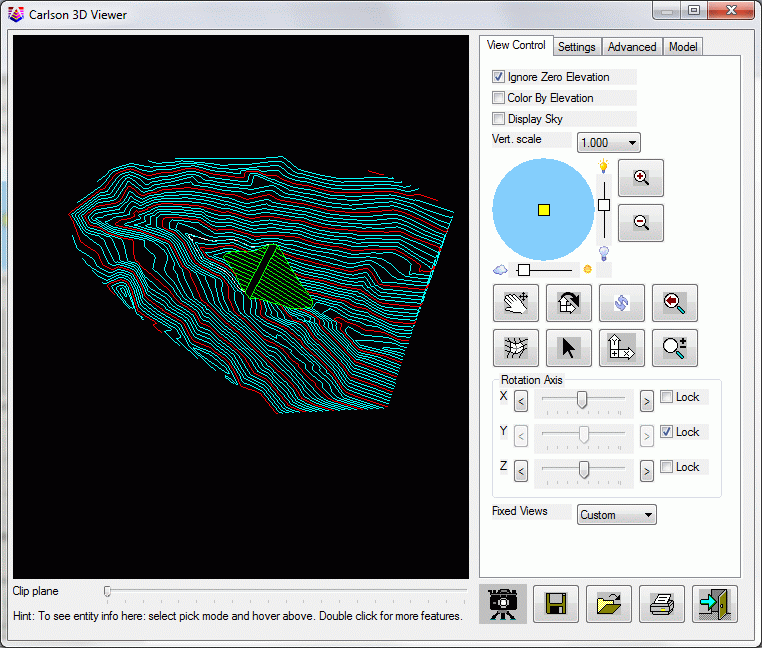
The main trick is to move the X-Axis bar to the left. Avoid the Y-Axis dial for now, and then grip on the Z-Axis dial and move it back and forth relatively fast, or just click on the Z-Axis arrows and watch things move slower. It's like you are in a helicopter over the site. Here's an example:

9 Exit the 3D Viewer. Now choose 3D Polyline by Slope on Surface, found under 3D Data > 3D Polyline Utilities.
Enter the polyline layer
<SLOPE_PLINE>: press OK
(to accept this)
Now select the grid file. The file is Topo-d.grd.
Limiting length for polyline (Enter for
none): press Enter
Pick origin point of 3D polyline:
pick a point on the south side of the
top of the dam, just before it contacts the ground
Direction of 3D polyline
[<Up>/Down]? D
Direction of 3D polyline facing down slope
[<Left>/Right]? R
Slope format
[<Percent>/Ratio/Degree]: press
Enter
Enter design slope percent:
10
Your information should be similar to this:
Pick origin point of 3D polyline (Enter to end): press Enter (no more)
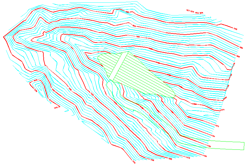
This created a smooth, 10% downhill grade 3D polyline, as shown, which we can use to construct a maintenance road up to the dam.
10 Offset 3D Polyline. This is a Carlson specialty; a high-powered Civil Design feature. In short, you can work in 3D because you can offset and manipulate 3D polylines using Carlson. So Select Offset 3D Polyline, under 3D Data > 3D Polyline Utilities.

press OK to the above dialog
Vertical/<Horizontal offset
amount>: 30 (for a 30' wide
road)
Percent/Ratio/Vertical offset amount
<0>: press Enter
Select a polyline to offset:
pick our new 3D polyline
Select side to offset: pick into the hill, to the left or SW
Select a polyline to offset (Enter for
none): press Enter (for no
more)
This creates the other side of the road parallel, but not joined yet. For that we use Join Nearest.
11 Select Join Nearest under the Edit pulldown menu. A dialog appears which you need to fill out as follows:
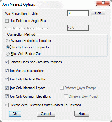
The most important aspect is to click Directly Connect Endpoints, and tolerate the fact that they are 30' apart by allowing for a Max separation to join of 31. That way, they will join! Click OK.
Select lines, arcs and unclosed polylines
to join. pick both sides of the
road one at a time, carefully avoiding picking a contour
If both the edge of roads are picked and highlighted, hit Enter to
avoid additional selections.
If a contour is picked, press ESC to exit the command and start over, or press R for remove, pick it to remove it from the selection set, then A to Add, and pick again on the road.
Tip: This may be obvious, but when it is difficult to pick what you want, because several objects are nearby or overtop what you want, it pays to do View, Window and zoom in closer, followed by View, Previous after you are done.
We have a road, or at least a sloping pad, seen below:
12 Pad Template is one of the more diverse and powerful commands in Carlson. We will use it here to make a simple cut and fill slope from our road pad. We will go 0.5:1 in cut, but 1:1 in fill. You might think a 2:1 in fill is better, but remember, our hillside edge of road (the original edge) follows very closely to the hill itself, as designed. If it cantilevers out a few inches, and the natural slope of the ground is 1.5:1 (which it is!), 2:1 will never catch, and we will create big fill areas. So we will go with 1:1 in fill, and get very tiny, quick tie-ins in those few cases where there is any fill at all.
Pick Design Pad Template, a command under the Surface menu. A dialog appears. Use the standard entries, as shown below:
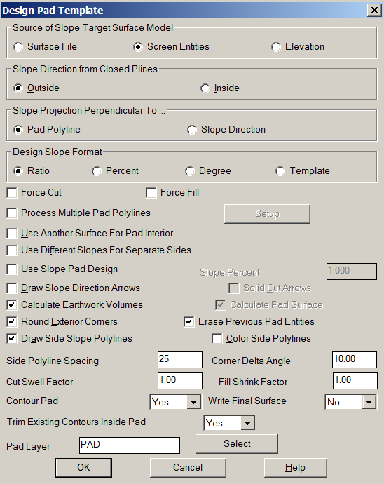
Click OK. Pick two limit points of pad disturbed area. Another dialog appears. Make sure the entries match what is below:
Click OK.
Pick the pad polyline: pick the road pad
Enter the fill outslope ratio
<2.0>: 1
Enter the cut outslope ratio
<1.0>: 0.5
Calculate earthwork volumes
[<Yes>/No]? Y
A report is produced similar to Valley Pond. Review and Exit
it.
Adjust parameters and redesign pad
[Yes/<No>]? N
Write final surface to grid file
[Yes/<No>]? Y
Store to the file Topo-f, for Topo final.
Trim existing contours inside pad perimeter
[Yes/<No>]? Y
Retain trimmed polyline segments
[Yes/<No>]? N
Contour the pad [<Yes>/No]:
N
Pick pad polyline:
Processing edge 26508, intersections found 149
Calculating grid elevations ....
Fill outslope ratio <2.000>: 1
Cut outslope ratio <1.000>: 0.5
Processing edge 388, intersections found 27
Calculating grid elevations ....
Processing cell
...
Adjust parameters and redesign pad [Yes/<No>]? n
Reading the selection set ...
Retain trimmed polyline segments [Yes/<No>]? N
Updated 16 entities.
Reading points... 271
Inserting points...
Inserted 271 points
Inserted 490 breakline segments
Analyzing TIN structure...
Intersecting inclusion polylines ...
Inserting intersection points ...
Contouring elevation 1485
Checking for Self-Crossing Contours ...
Checking Contours ...
Inserted 1464 contour vertices.
Join final contours with existing [<Yes>/No]? Y
Reading the selection set ...
Reading the selection set ...
Joining ...
Joining ...
Join linework for different layers CTRINDEX and CTR at
15131.07,79492.97.
Use first or second layer name or pass
[<First>/Second/Pass]?
Select the 3D Viewer Window option, under the View pulldown to view the drawing now with a road. This completes the Lesson 6 tutorial: Contouring, DTM and Design.