
1 Click the icon to launch Carlson. Once in the program, exit the Startup Wizard if it appears.
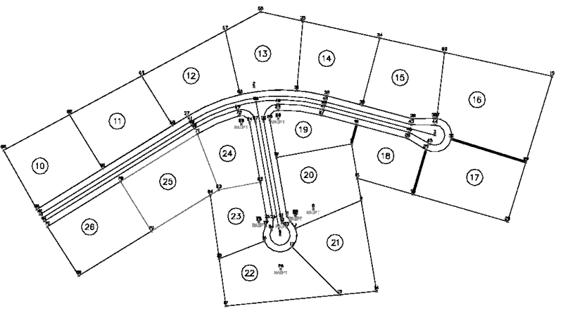
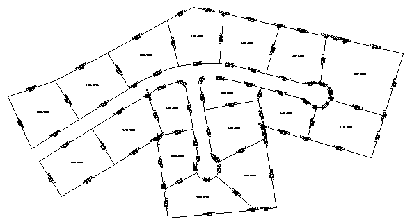
2 Once in Carlson, click Open under the File pull down menu. Look for the file Plat4.dwg (this file should be located in the "C:\Carlson Projects" folder) and click on it. When it lights up blue, as shown below, it will appear in the Preview Window at right. It should look like the open-sided property shown here. You search for the file as you typically would in Windows, clicking the yellow "Up one level" button to go to the parent folder of the current folder, or by clicking the adjacent down arrow to find the desired path in the full tree of folder locations.
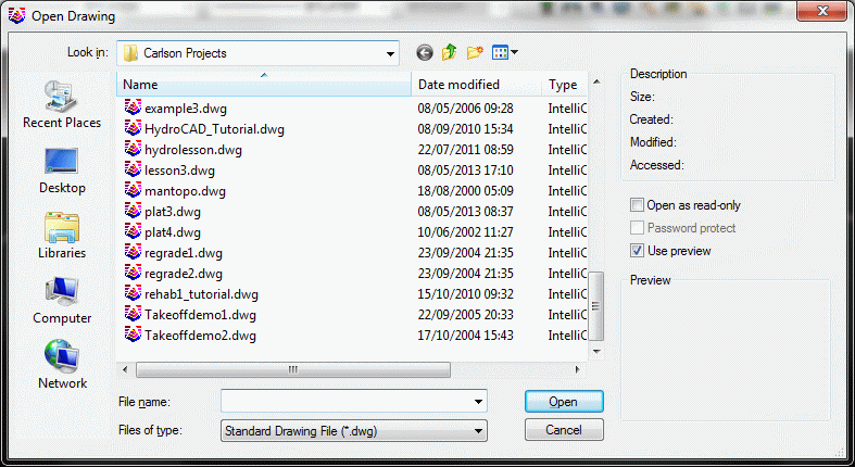
Now click Open to select and open the file Plat4.dwg.
3 Enter & Assign a Starting point for the Street Centerline. Select Draw-Locate Points, found under the Points pull down, and obtain the dialog shown below:

Click off the prompting and labeling for Descriptions, Elevations and Locate on Real Z Axis (make them blank as shown). Up top, change the symbol to SPT10 by picking Select at the very top of the dialog, and choosing symbol SPT10 from the dialog of symbol choices (not shown here). Also, verify that Automatic Point Numbering is clicked on, that the Starting Point Number is 1, that the layer is PNTS. Match these entries (which are mostly the default conditions) and click Enter and Assign at the lower left.
Prompting will appear at the bottom of the screen. We will enter the starting point as follows:
Enter North(y): 4809.17
East (x): 4391.28
The program will recognize that you have not yet started a coordinate file, so click the New tab and enter the File Name as Plat4.crd (which should be the default). If you enter Plat4, you do not need to enter the extension .crd. The program will add extensions automatically. You will see this:
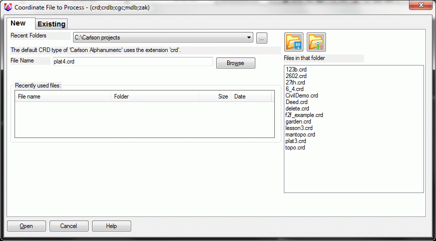
Click Open. You will be prompted again:
Enter North(y): press Enter (for no more points; we are done)
4 Traverse from PI to PI (to the two endpoints of our centerline). Select Traverse under the COGO menu, or alternately just enter T at the command line. (T is a hot key. Other hot keys are I for Inverse and SS for Sideshot). Reply to the prompts as follows:
Traverse, Line OFF, RAW FILE OFF
Exit/Help/Options/Arc/Points/Line/SideShot/Inverse/Angle-Bearing
Code <7>: 1
Enter Bearing Angle (dd.mmss)
<90.0000>: 58.1848
Points/<Distance>: 736.73
N: 5196.15 E: 5018.19 Z:
0.00
Exit/Help/Options/Arc/Points/Line/SideShot/Inverse/Angle-Bearing
Code <1>: E (to exit)
You could keep on traversing, but we will stop here to review. You have created point 2, traversing NE from point 1. To review, code 1 is for NE, 2 for SE, 3 for SW, 4 for NW, 5 for Azimuth, 6 for Angle Left, 7 for Angle Right, 8 for Deflection Left and 9 for Deflection Right. This is the standard way that traverses and sideshots are entered in Carlson with a code entry (followed by Enter), then the angle or bearing entry (followed by Enter). Lesson 1: Entering a Deed, presented another method, where the angle and bearing are together in the form of 158.1848. That is a rare form, designed to save keystrokes, and used primarily only in Enter Deed Description. Now you have been exposed to both!
5 Line On/Off. Click Line On/Off under the COGO menu to turn on simultaneous linework with traversing. This command toggles on and off each time you click it, with the On status indicated by a check mark. Now repeat the Traverse command. Try T for Traverse this timTe, entered at the command line.
Traverse, Line ON, RAW FILE
OFF
Exit/Help/Options/Arc/Points/Line/SideShot/Inverse/Angle-Bearing
Code <1>: 2
Enter Bearing Angle (dd.mmss)
<58.1848>: 75.0627
Points/<Distance>: 553.69
N: 5053.85 E: 5553.28 Z:
0.00
Exit/Help/Options/Arc/Points/Line/SideShot/Inverse/Angle-Bearing
Code <2>: E (to exit)
6 Draw a Polyline from Point 1 to Point 2, and connect the segments with Join Nearest. We could have turned linework with traverse on before we got started, but now we will do it after-the-fact. So choose 2D Polyline under Draw. Some users like to simply type in 2DP at the command line that starts the Polyline command. If the Polyline 2D Options dialog box appears, set the values shown below and click the OK button.

[Continue/Extend/Follow/Options/<Pick point or point
numbers>]: 1
[Arc/Close/Distance/Follow/Undo/<Pick point
or point numbers>]: 2
[Arc/Close/Distance/Extend/Follow/Line/Undo/<Pick point
or point numbers>]: press Enter (to
end)
Now we have two line objects. The first, from point 2 to point 3 is a pure Line. The second, from point 1 to point 2, is a true Polyline (even though it is only one segment long). It is officially a LWPOLYLINE, a lightweight polyline. This can be verified by picking it using the List command under Inquiry. Polylines are linked combinations of one or more line segments that behave as one unit. We encourage use of polylines versus lines because they offset as a unit, will take on a thickness or width, are easier to select and have superior editing capabilities. A line can be turned into a polyline by picking Polyedit under Edit, picking the line, and answering Y to the question "Do you want to turn it into one? <Y>". To join the polyline and line objects into a single polyline, choose the very useful command Join Nearest, found under Edit.

The defaults are good. Just click OK.
Select lines, arcs and unclosed polylines
to join.
Select objects: pick the polyline from
1 to 2 and the line from 2 to 3, and then press Enter for no
more
Now, see the grips on the new polyline by picking it with the cursor. See how the whole thing highlights? That is proof that it is joined up as a polyline.
7 Design a Curve with a 500' Radius. Under Draw, pick Arc and slide over to 2 Tangents,Radius.
Radius of Arc <0.00>:
500
[nea] Pick Point on 1st Tangent Line:
pick on the 1st polyline segment
closer to point 2
[nea] Pick Point on 2nd Tangent Line:
pick on the 2nd polyline segment close
to point 2
The arc draws in, and the centerline remains a polyline, now with 3 segments.
8 I for Inverse. Entering I for Inverse, at the command line, is a handy way to get on a point to begin another traverse. Practice inversing. Enter I. Inverse from point 1, then to point 2, then to point 3 then back to 1. But you can also inverse (go to) a snapped position on a line or polyline, such as the midpoint of an arc. Let's do that, because we want to traverse south from the midpoint of the arc. Enter I, for Inverse.
Calculate Bearing & Distance from
starting point?
Traverse/SideShot/Options/Arc/Pick point or point number:
MID (for midpoint snap of) select the
arc
Traverse/SideShot/Options/Arc/Pick point or
point number: T (for
traverse)
Traverse, Line ON, RAW FILE OFF
Exit/Help/Options/Arc/Points/Line/SideShot/Inverse/Angle-Bearing
Code <2>: press
Enter
Enter Bearing Angle (dd.mmss)
<75.0627>: 10.11
Points/<Distance>: 400
Exit/Help/Options/Arc/Points/Line/SideShot/Inverse/Angle-Bearing
Code <2>: E (to exit
traverse)
Notice that you can transition from inverse, to traverse, to sideshot, etc. with these COGO options. We were in inverse, but we did T for traverse, and could have done I for inverse to return to inverse. This cuts down on keystrokes, and adds to the sense of fluidity of the software.
9 Turn a Line into a Polyline with Polyedit. The command Offsets & Intersections requires pure polylines, not lines, to execute. So, since we had Line On with the last traverse, we have created a line. To use this in street design, we need to convert it into a polyline. Select Polyedit under the Edit pull down menu.
Select polyline or [Multiple]:
pick the side road line Object selected is not a polyline
Do you want to turn it into one? <Y> press Enter
Enter an option [Close/Join/Width/Edit
vertex/Fit/Spline/Decurve/Ltype gen/Undo]: press Enter
10 Offsets & Intersections. Under the Area/Layout > Layout Utilities menu, select Offsets & Intersections.
Select all PRIMARY road polylines.
Select objects: press Enter (we
will consider both these subdivision streets secondary)
Select all SECONDARY road polylines.
Select objects: pick the main
centerline
Select objects: pick the side road
Select objects: press Enter (for no more)
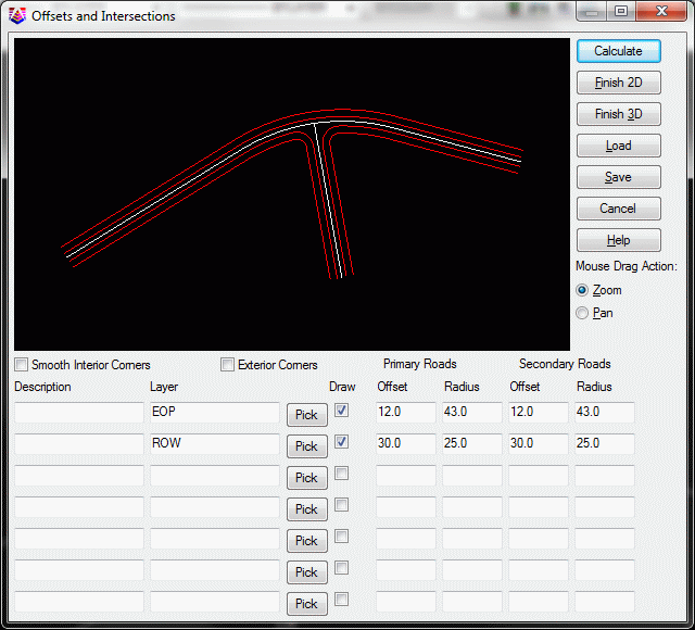
The street intersections are presented in a dynamic dialog as shown above. Try experimenting with different radii under the Secondary Roads column, then clicking Calculate. The streets will re-draw in the upper graphical area. But after experimenting, change the four values under Secondary Roads to those shown (ignore Primary Roads -- those don't apply here), and click Calculate. Then click Finish 2D. Note the drawn-out street intersection.
Now select Drawing Inspector under the Inquiry menu, right click and make sure Layer is checked. Hover over the outside polyline (it is layer ROW). Hover over the next polyline in from the outside (it is layer EOP). For example, if you had clicked off EOP under the Draw column in the above dialog, the edge-of-pavement polyline would not have drawn.
11 Standard Cul-de-Sac. Under Area/Layout > Layout Utilities, select Cul-de-Sacs. You may want to zoom into the area of the bottom center, near point 4. When finished with the procedure below, zoom back out.
Select all offset polylines to end with
cul-de-sac.
Select objects: form a crossing
selection from right to left across the lower side road, selecting
all 5 polylines (ROW-L, EOP-L, CL, EOP-R, ROW-R)
Select objects: press Enter (for no more)
Pick cul-de-sac center projection onto
centerline: END (for endpoint
snap)
of pick near the
endpoint of the centerline of the lower side road near point
4
Make sure the pick is on the centerline polyline, or the routine
will say the centerline not found.
This brings up the following dialog:
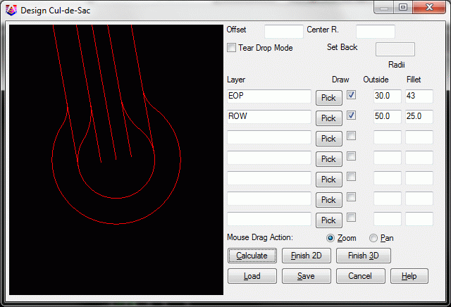
Again, you can change the Fillet Radius and the Outside Radius on the EOP or ROW, hit Calculate, and check out its effect (don't make the Outside radii too small or it will fail to Calculate if there is no workable solution). Set values as shown above. Then click on Finish 2D.
12 Teardrop Cul-de-Sac. Now select the Cul-de-Sacs routine again, under Area/Layout > Layout Utilities.
Select all offset polylines to end with
cul-de-sac.
Select objects: form a crossing
selection pick from right to left across the right main
road, selecting all 5 polylines (ROW-L, EOP-L, CL, EOP-R,
ROW-R)
Select objects: press Enter (for no more)
Pick cul-de-sac center projection onto
centerline: END (for endpoint
snap)
of pick the
endpoint of the centerline of the lower side road near point
3
For a teardrop cul-de-sac, fill out the dialog as follows, then click on Calculate and Finish 2D.

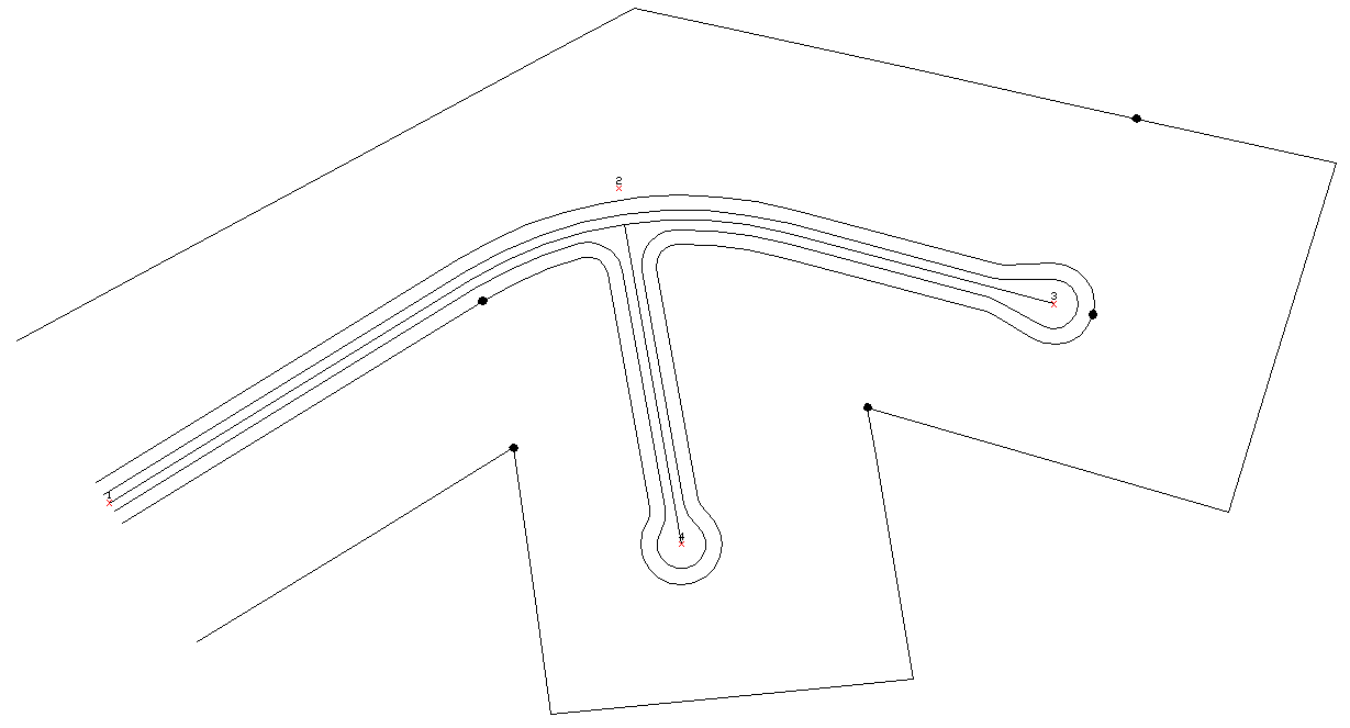
Teardrop cul-de-sacs allow moving vans and other large vehicles more turning room, and have been popular in the Cincinnati area, for instance. Our drawing now appears as shown below, with the exception of the filled reference dots.
13 Let's make a layer called LOTS using Layer Control found under View. It's a good idea to create a layer and set it current before beginning the design process. Select Layer Control and obtain the following dialog:

Click on for New layer. When Layer1 highlights, as shown at bottom of list, type over it with LOTS, then click under the Color column and change the color to Magenta. Then click the (Set) Current button up top to make this layer current. Then click OK to exit the dialog.
The Lot Layout routine under Area/Layout, Layout Utilities works nicely with reasonable polylines that run roughly parallel. Our goal is to make 1-acre lots. Lots of zigs, zags, and jogs in the polylines cause the perpendicular offset logic to fail to find a solution (lots will radiate perpendicular from the front polyline in Lot Layout). Not only should the front and back lines run opposite each other, but they should end at some point before the calculation runs into difficulty with impossible math.
The outer R-O-W polyline currently runs left-to-right, goes around both cul-de-sacs and returns right-to-left in one, connected polyline. We need to break it near where the filled dot is pointing. It should be easy to lay out lots along the upper portion of the subdivision, as long as we stop to break the R-O-W polyline before it turns and runs back through the lower, more complex frontage and back property portions.
Under Edit, select Break, and slide over to At Selected Point. You will select using the filled dots, shown on the plan above, as references.
Select Line, Arc, or Polyline at break
point: pick near the filled dot on the
outer boundary polyline
Repeat the command for the ROW polyline.
Select Line, Arc, or Polyline at break
point: pick the far right end of the
Teardrop cul-de-sac R-O-W polyline
To prove you have broken the polylines in two, click on the R-O-W polyline on the south side (only the south portion should highlight), then click on the north R-O-W polyline (which we will use as our frontage polyline in the command Lot Layout). Then press the ESC key twice, which gets rid of the grips, as does zooming or panning.
14 Select Lot Layout under Area/Layout > Layout Utilities. A dialog appears:
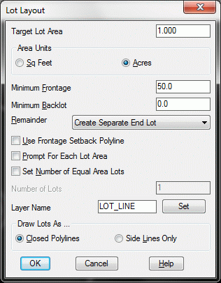
Fill out as shown. In particular, change the Remainder to Create Separate End Lot so that we force 1.000 acre lots and don't just get equal lots of some size such as 1.0017 (because the remainder lot that would not fit was added onto all lots).
Making Closed Polylines means that our side lines will be doubled up, each lot sharing a side line. Click OK.
Select front polyline: pick north R-O-W
Select back polyline: Pick northernmost polyline the back property
line
The 1.00 acres lots are laid out as far as is possible. You may get a small lot at the end of the row, which you would erase.
15 Applications of Reverse Polyline. We can get more Lots from Lot Layout, by doing the lower R-O-W at the left side of the drawing, and picking the southern back polyline. Let's try. Select Lot Layout under Area/Layout > Layout Utilities. Use same dialog entries. Select the front polyline as the southern edge of the road R-O-W, near the left side of the drawing. Select the back polyline as the southern property line. Oops! Nothing drew. It was unable to calculate. It turns out that the direction of the polyline is important. Run Inquiry > Drawing Inspector and check on Polyline Direction. You will see the southern R-O-W polyline starts way off to the right, so the program was not even considering where we were looking! We need to reverse the direction of the southern R-O-W polyline so it starts on the left side. Select Reverse Polyline, found under the Edit pull down, sliding over from Polyline Utilities. It prompts:
Select polyline or line to reverse: pick the southern R-O-W polyline
The polyline now reverses direction, goes left-to-right, and shows phantom direction lines (which are automatically removed when the command ends). Now repeat the Lot Layout command as outlined in the beginning of Step 15, and we get one new lot out of the exercise, as shown below. If you get a second wedge shaped lot, erase it.
16 Break at Intersection. The lower back property line is still continuous. We can work with it in small pieces rather than as one big polyline. Say we want to break it at the inside corner identified by the arrow above. To do this, select Edit pull down, Break, sliding over to At Intersection. Prompting:
Select Line, Arc, or Polyline to
Break: pick the south property
line
[app on] Pick Intersection to break at:
move the cursor to the intersection point
indicated in step 12, look for the INT snap to appear as you
approach the exact corner (which is an intersect), then click
there
17 Draw a Polyline from the corner indicated by the filled dot to the beginning of the R-O-W arc, also indicated by a filled dot in the previously referenced graphic. Select 2D Polyline under Draw and click on the OK button to dismiss the dialog box if it appears.
Pick point or point numbers:
END (type in end for the endpoint
snap)
of pick the inner
back property corner
Undo/Arc/Length/<Pick point or point
numbers>: END (type in end for the
endpoint snap)
of Pick the
beginning of the Arc (it will show endpt when you get close
to the true start of arc) pUndo/+/-/Arc/Close/Length/<Pick point or point
numbers>: press Enter (to
end)
18 Area by Interior Point. We have just created a new lot, but the lot is not defined by one, single, closed polyline. If we want to verify its area, however, we can still use the command Area by Interior Point. Select Area by Interior Point under Area/Layout.
Pick point inside area perimeter: pick inside our new lot
SQ. FEET: 40997  SQ. YARDS: 4555.2  SQ. MILES: 0.0

ACRES: 0.94  PERIMETER: 830.5
Pick area label centering point:
press Enter here to avoid
labeling
Pick point inside area perimeter (Enter to
end): press Enter to end the
command
The lot is less than one acre. We will set as a goal to extend
its lower boundary to the right to obtain one acre. That is
accomplished by using the command Hinged Area. But Hinged Area
works best if we have a nice, closed polyline for the new lot. We
can get one using the command Boundary Polyline.
19 Boundary Polyline. From
the Draw menu, select Boundary
Polyline.Enter layer name for
boundary polylines <LOTS>:
Enter snap tolerance
<0.0001>: select
OK
Select polylines.
Select objects: pick all the polylines
that surround our new lot and then press Enter
Pick an internal point: pick a point in the Lot interior
Pick an internal point (U-Undo, Enter to
end): press Enter
This creates a new closed polyline, in the current, LOTS layer (magenta).
20 Select Hinged Area under Area/Layout > Adjust Areas.
Define area by points or closed polyline
[Points/<Linework>]? press
Enter (for linework)
Select polyline segment to adjust:
pick on the right-side line (make sure
you pick the Lot polyline rather than the single polyline
vector)
Select hinge point [endp]: pick on the upper right hinge point (see
arrow)
Keep existing polyline
[Yes/<No>]? N
Area: 40997.20 S.F, 0.9412 Acres
Remainder/Acres/<Enter target area (s.f.)>:
A (for acres)
Remainder/SF/<Enter target area
(acres)>: 1.0
The new lot draws, as shown below:
21 Next, use the Erase command to remove the segment that is pointed to above with the text Click on This Side.
22 Make two more Lots with polyline command. Instead of using Draw, 2D Polyline, we will use the straight AutoCAD polyline command. At the command line, enter PL.
Specify start point: END (type in the endpoint snap)
of pick the
endpoint (which is the lower right corner of the new
lot)
Current line-width is 0.00
Specify next point or [Arc/Halfwidth/Length/Undo/Width]:
PER (type in the perpendicular
snap)
to pick on the
R-O-W polyline to the right
Specify next point or
[Arc/Close/Halfwidth/Length/Undo/Width]: press Enter (to end)
Now for the second lot. Referring to the drawing below, repeat the PL command, and answer as follows:
Specify start point: NEA (enter the nearest snap)
of pick on the
property line anywhere near the circled point 1 (no need to
be exact)
Current line-width is 0.00
Specify next point or [Arc/Halfwidth/Length/Undo/Width]:
PER (type in the perpendicular
snap)
to Pick on the
R-O-W polyline near circled point 2
Specify next point or
[Arc/Close/Halfwidth/Length/Undo/Width]: press ENTER (to end)
The drawing appears below:
 Per
Per23 Issue the Break at Intersect command (step 16), and break the back property polyline and the cul-de-sac R-O-W polyline at the intersections with our newly drawn polyline from step 22. Repeat this command, and break the back property polyline at the filled dot to the right of the "Sliding Side Area" label below.
24 Repeat Lot Layout with the same entries as before. The front and back polylines to select are shown below, along with the results. This gives us two more usable lots.
Next, use the 2D Polyline command to generate a segment (above the "Sliding Side Area" label below) that runs from the ENDpoint of the corner to a point PERpendicular to the R-O-W line. Next, use Boundary Polyline under the Draw menu to create a closed boundary inside it. To do this, select each boundary line in the segment, press Enter twice, pick an interior point, press Enter again.
Erasing the original segment you placed is a little tricky since
the newly formed polyline is on top. When two pieces of geometry
lie on top of each other, Carlson will take the one created last.
Issue the Erase command,
then hold down the control key while picking the segment above the
"Sliding Side Area" label. When the single segment highlights,
press enter to erase it, leaving the boundary polyline. Also note
you can hold the shift key, place the cursor over object on screen,
and press the space bar to cycle through entities in order to erase
objects on top of each other.
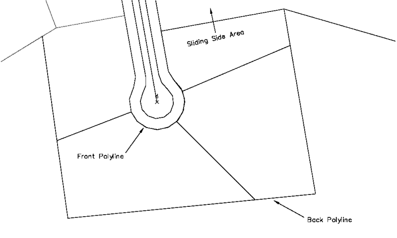
25 Sliding Side Area. Because we have a small closed polyline, we can investigate another area command, the Sliding Side Area. As shown in the graphic above, we want to slide the north side of the last, smaller lot parallel to its current bearing such that the lot will contain 1.00 acres. Select Sliding Side Area under the Area/Layout > Adjust Areas pull down.
Define area by points or closed polyline
[Points/<Linework>]? press
ENTER for Linework
Select polyline segment to adjust:
pick the north side of the lot above
(shown here containing the words Sliding Side Area)
Keep existing polyline
[Yes/<No>]? press
ENTER
Define new line by selected line,
another line, angle or points
[<Selected>/Line/Angle/Points]? press ENTER for Selected
Area: 20375.31 S.F, 0.4678 Acres
Remainder/Acres/<Enter target area (s.f.)>:
A (a for acres)
Remainder/SF/<Enter target area
(acres)>: 1.0
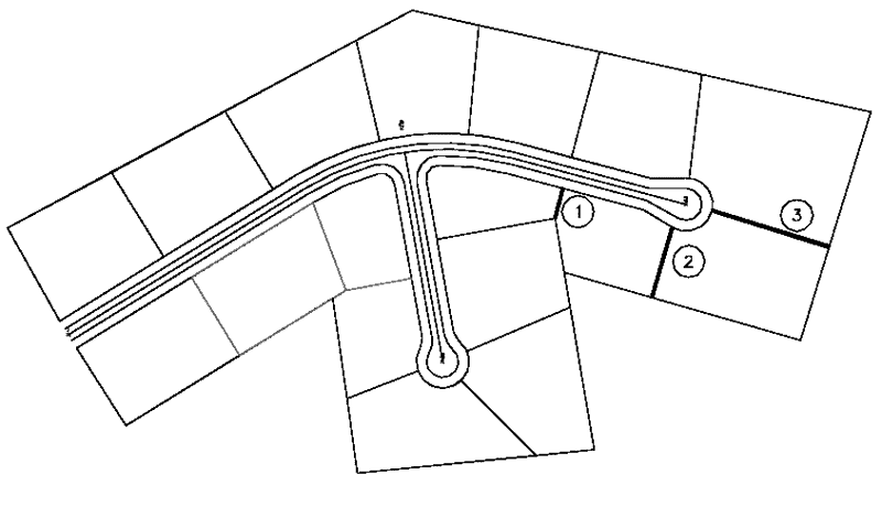
26 Complete the remaining Lots. Using the 2D Polyline command, under Draw, use endpoint snaps and perpendicular snaps (end and per) to draw the final 3 polylines, shown below marked 1, 2 and 3 for reference.
It may not be the most aesthetic subdivision, but we applied a lot of tools making it. But we're not done. There's some real automation ahead.
27 Create Points from Entities. We have designed a subdivision, in effect, without point numbers. This is the beauty of CAD. But we need to make point numbers in order to stakeout the subdivision. To do this, select Create Points from Entities, under COGO. The following dialog appears:
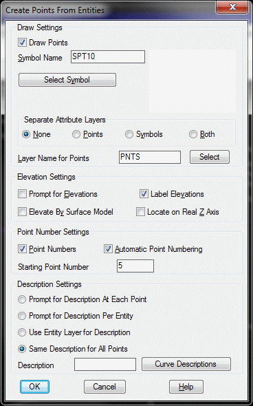
Set the starting point number to 5, verify the dialog as shown, and click OK. A second dialog, covering what entities to capture, appears next. Stick with the default settings and click OK.

When it asks, Select objects, type in All. Press Enter for no more selections, and Enter again. All the point numbers for stakeout are created.
28 Number the lots, clockwise from the upper left, using the command Sequential Numbers. Under Draw, select Sequential Numbers. This dialog appears:
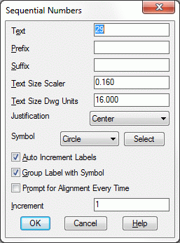
Click on the Select button to select a desired symbol to circumscribe our sequential numbers.
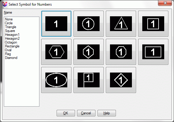
Choose the circled text and click OK.
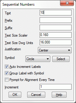
Set the Text value to 10 and the Text Size Scaler to 0.16 as shown. Then click OK.
Pick point for label position:
pick near the center of the first upper left
lot
Pick point for label alignment:
press F8 for <Ortho on>, pick to the
right
Now pick near the center of all of the lots, going clockwise.
When done, and back to the command line, press F8 again to set Ortho off.
The resulting drawing, with point numbers, is shown below:
29 Lot File by Interior Text. Official lot files can be created whenever a lot number or name exists within a lot as the sole text (other text may be present but could be frozen). So we will play it safe and first freeze the point number layer. Before we do, take note of the point number assigned to the NW corner of Lot 10. In our case, it is point 73 (it may be different in your case, depending on how you selected the objects in the command Convert Entities to Points).
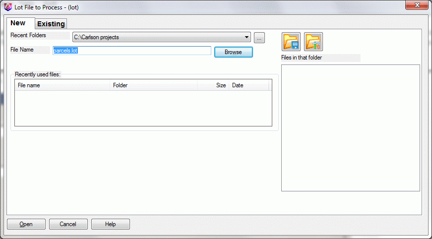
Under View, select Freeze Layer and pick on one of the point numbers. Now go to the Area/Layout pull down, select Create Lots and slide over to select Lot File by Interior Text. Supply the Lot File to Process value as shown below and click the Open button.
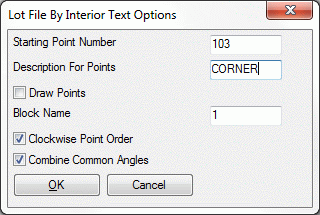
A dialog box will appear. Be sure that is says Block Name 1. Click OK.
Select lot lines, polylines and text.
Select objects: pick the lots and the
lot numbers
The Lot File will be created. Before we look at the Lot File, let's finish up and perform area annotation on the upper Lots with the Area by Interior Point command.
NOTE: If we had not made points at all lot corners using Convert Entities to Points, the Lot File by Interior Text would create points at the Lot corners. This is the reason for the Starting Point Number prompt. If points are found, no new ones are created. Lot files must have points at all the corners.
30 Area by Interior Point. Select Area Defaults under Area/Layout, and remove the Sq. Feet entry leaving only the Acres item and verify it is set to plot to 3 decimal places and click OK.

Now choose Area by Interior Point under the Area/Layout pull down menu and pick inside Lots 10 through 16, as shown below:
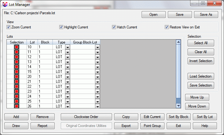
31 Select Lot File Manager under Area/Layout, and the Lot Manager dialog appears:
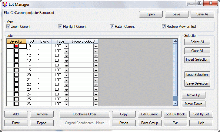
Pick on Lot 10 and click Report. This will lead to the Lot Report dialog box.
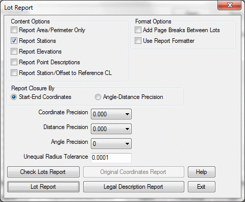
Be sure that your setting are as shown above, and then click Lot Report.
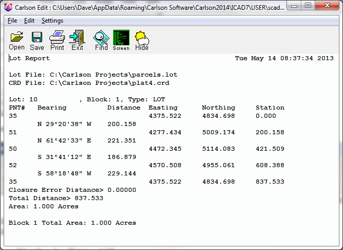
This dialog is typical of the many Carlson Standard Report Viewer dialogs. You can click on one or more lines, highlight them and hit the delete key on the keyboard, and these lines will delete. You can edit lines directly in the dialog. You can also save the report to disk with the Save icon shown above. To exit, click the Exit icon. The Lot Manager dialog box returns.
32 The Edit Current option within the Lot Manager dialog box can be used to describe a lot by different point numbers, or to assign a lot to a different block. This is explained here and shown below for reference purposes only.
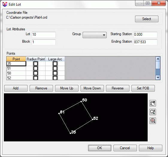
Under Selection, select a lot to edit. Click Edit Current. You will get this dialog. Note the graphic display in the lower half, which map the Points listed above. If you've opened this dialog box, click Cancel and the Exit on the Lot Manager dialog box.
33 Re-Drawing Lots after Editing Points. Let's assume you actually changed the point numbers that define Lot 10. That would cause the lot to draw differently. Also, you could simply alter the coordinate values of a point in the current lot file. That would also cause the lot to draw differently. Let's take the latter approach. Remember point 73? In our case, it is the NW corner of lot 10 (your case may be different as stated above). So select Edit Points under the Points pull down menu. A spreadsheet appears. Scroll down to point 73 (or whatever point is your NW corner of Lot 10).

Click on the Northing and edit it to 5050. This is for illustration purposes. In reality, you might be fine-tuning your subdivision design points. As long as the same points define the lots, you are, in effect, making a ready-made new drawing. Now select at the top of the dialog File, then Save and Exit.
34 Draw the Lot File. Before we draw the lot file, save your drawing by selecting Save under the File pull down menu. Then choose New, exit the Startup Wizard (if it appears), and go straight to Lot File Manager, found under the Area/Layout pull down menu. Lot Manager provides the tools for drawing lot files to the screen.
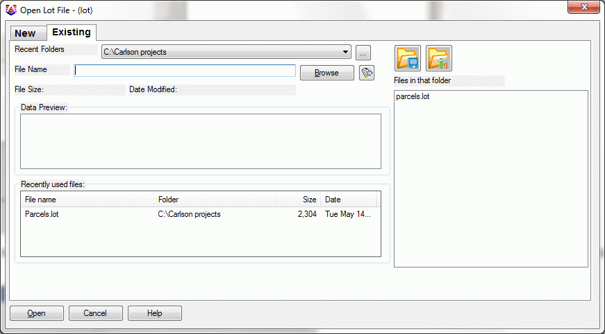
Click the Existing tab and select the parcels.lot file and click Open. Select your existing Plat4.crd file that you created earlier. When the Lot Manager dialog appears, choose all Lots by clicking Select All. Then click Draw.
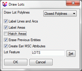
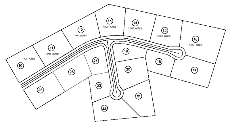
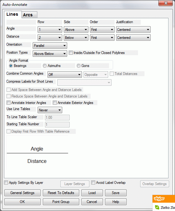
Apply settings required or as image above and click OK to the Draw Lots dialog box. This leads to the Auto-Annotate dialog, shown below. Use the settings shown here. Click OK.

Next comes the Area Defaults dialog, as seen in Step 30. Fill out exactly as shown in Step 30.
Click OK and then Exit. This leads to the plot shown below, created entirely from stored Lot Files, and showing our revision of Lot 10.
This completes the Lesson 4 tutorial: Intersections and Subdivisions.