Lesson 17: GeoTech Drillholes and Strata
This lesson creates and processes drillhole
data in the GeoTech module.
Step 1 (Complete the "Takeoff/SiteNET Basics"
Tutorial):
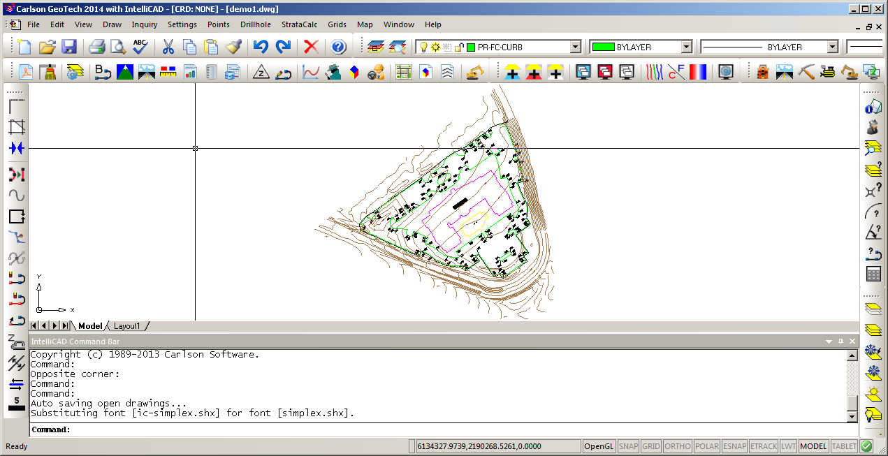
This drillhole lesson builds on the resulting drawing
"takeoffdemo1.dwg" from the previous tutorial. Before continuing
with this tutorial, run through Steps 1-8 of the tutorial
"Takeoff/SiteNET Basics".
When the "Takeoff/SiteNET Basics" tutorial is completed, we're now
ready to add drillholes.
Step 2 (Drillhole/Strata Settings):
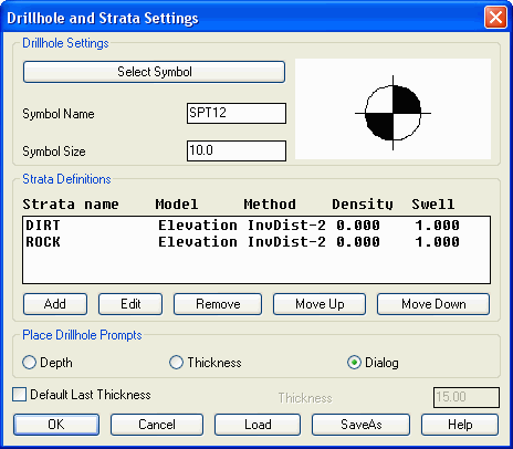
From the Drillhole menu, choose
Drillhole/Strata Settings or Define Drillhole. This command sets
the drillhole symbol and the default strata names. For this
tutorial, we are interested in rock quantities and we need to
define two strata: Dirt (material above the rock) and Rock.
Pick the
Add button which brings up another dialog that defines a strata.
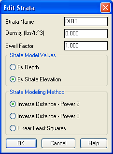
Enter a strata name of "DIRT" and a density of 125 which will be
used to calculate tons in the volume report. You can also have a
strata specific cut swell factor. The strata can be modeled either
by the elevations from the drillholes or by the depth from the
existing ground. In this case, we will model by strata elevation.
There are also 3 options of modeling methods. Linear Least Squares
extrapolates trends and allows for a strata model to create new
highs and lows, that don’t appear in the original drillhole data.
Inverse Distance will not carry trends and the calculated strata
model will never be higher or lower than the original drillhole
data. Inverse Distance uses a weighted average of the drillhole
data. In general, closer drillholes are weighted more than
drillhole farther away. Inverse Distance - Power 3 will weigh
drillholes less that are further away. Inverse Distance - Power 2
will weigh them more. When the dialog is filled out as shown, pick
OK.
Next, pick the Add button again. This time,
fill out the dialog with a strata name of "ROCK" and density of
150. Then pick OK.
The Strata Definitions in the main dialog need
to be in top to bottom order. To change the order, highlight a
strata name and use the Move Up or Move Down buttons. In this case,
we want Dirt then Rock. Click OK now from the main dialog.
Step 3 (Input Drillhole Data):
There are two different methods for entering drillhole data:
Drillhole Import and Place Drillhole. Drillhole Import reads the
drillhole data from a text file. This command supports customizing
the sequence of drillhole data fields to match the format of the
text file. Place Drillhole creates the drillholes at picked
positions in the drawing and enters the data in a dialog. For this
tutorial, we will use Place Drillhole.
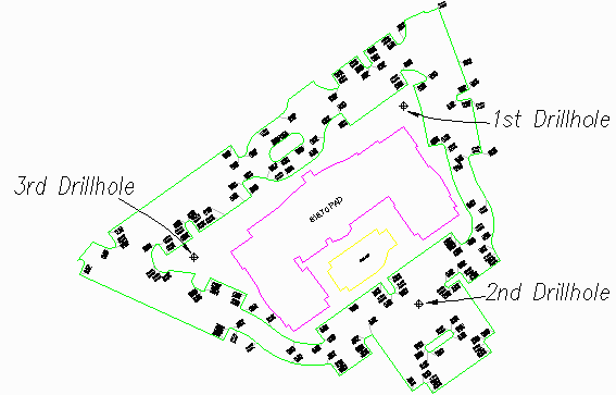
Run the Drillhole->Place Drillhole command. At the command line,
there is a prompt to pick the drillhole location. If you know the
coordinates for the drillhole, you can type in the easting,northing
instead of picking on the screen. In this case, let's pick a point
above the upper right of the main building.
Pick Drillhole Location: pick a point
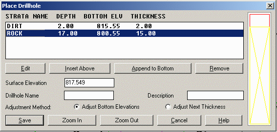
Then there is a dialog for entering the drillhole data. The surface
elevation is automatically filled in using the existing ground
surface model. The Drillhole Name and Description are optional. The
list of strata defaults to the strata defined in Drillhole/Strata
Settings. Each strata defaults to a thickness of zero. To set the
strata thickness, highlight the strata and pick the Edit
button.
For this case, highlight Dirt and pick Edit. This brings up the
Edit Strata dialog. The strata position can be defined by
thickness, elevation or depth. Setting any one of these fields will
update the other fields. For our dirt strata, fill in a thickness
of 2 and then pick OK.
Next, pick Rock from the strata list and pick Edit. For this
example, we only know the depth to the top of rock depth and not
the total rock thickness. We will treat all cut below the top of
rock as rock strata. So we will set the rock thickness deep enough
to be lower than the deepest cut on site. In this case, we will use
a rock thickness of 15. So in the Edit Strata dialog for rock,
enter a thickness of 15 and then pick OK.
After editing the rock strata, we are returned to the main Edit
Drillhole dialog. Pick the Save button.
Now let's locate two more drillholes using a different method.
Return Drillhole/Strata Settings dialog and change Place Drillhole
Prompts to Thickness. Also, check on Default Thickness and set it
to 15 feet, Press OK.
Now run Place Drillhole again and for the second drillhole, pick a
position in the lower parking lot. The command line will prompt you
to enter a dirt thickness, type in 1.5 and your drillhole is
created. For the third drillhole, pick a position left of the main
building. Enter a dirt thickness of 3.0, save, and enter to end the
command.
Step 4 (Make Strata Surfaces):
Now that the drillholes are in the drawing, to make the strata
triangulation surfaces, run the Drillhole->Make Strata Surfaces
command. There are no prompts for this routine. The strata surfaces
are modeled from the drillholes and saved with the project. The
file names for the strata surfaces use the drawing name plus "-ch#"
where the # is the strata sequence number. For this example, the
file names will be "takeoffdemo1-ch1" for bottom of dirt and
"takeoffdemo1-ch2" for bottom of rock.
Now that the strata surfaces are created, there are several Takeoff
routines that will use these surfaces such as:
- Calculate Total Volumes
- Calculate Volumes Inside Perimeter
- Cut/Fill Labels
- Surface Inspector
- Quick Profile
- Trench Network Quantities
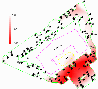
Step 5 (Draw Strata Cut Color Map):
From the Drillhole menu, pick Draw Strata Cut Color Map. This
command compares the design surface with the strata surface to make
a cut color map of the cut depths for the strata. This command is
one way to verify that the strata surfaces are modeled
correctly.
There is a dialog to select which strata map to draw. Choose Rock
and pick OK. Then there is an option to draw a cut depth legend.
Pick a position for the legend in the upper left of the site and
use the defaults for size and zone summary.
Step 6 (Calculate Total Volumes):
From the Construction module, run Takeoff->Calculate Total
Volumes command. In Civil, this command is found under SiteNET.
When strata surfaces are defined, the volume routine will breakout
the cut volume into the different strata. "Depth Zones" can also be
defined in this command. The resulting dirt and rock quantities are
shown in the report.