Lesson 21: GeoTech Reports
This lesson creates and reports drillhole
data.
Step 1 (Load and View Example Drawing):
This drillhole lesson builds on the resulting drawing called
Takeoffdemo1.dwg from the Takeoff tutorial lesson. Use File >
Open to open the Takeoffdemo1.dwg from the Carlson Projects
folder.
For mapping the drillholes, we don't need to see all the drawing
layers. Run View > Freeze Layer By Pick and pick on a
contour polyline and a curb elevation label. In this case, the
contours are on a few different layers. So run Freeze Layer By Pick
and keep picking contour polylines and labels until all contours
are gone.
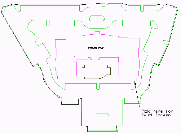
Next, let's orient the drawing so that the building is shown
straight across. Run View > Twist Screen > Line, Polyline
or Text and pick on the northeast end of one of the building
segments running northeast as shown.
Step 2 (Drillhole and Strata Settings):
From the Drillhole menu, choose Define
Drillhole. This command sets the drillhole symbol and the
default strata names. For this tutorial, there are two strata in
the drillholes: Clay and Limestone.
Pick the Add button which brings up
another dialog that defines a strata. Enter a strata name of
"CLAY". For this tutorial, the rest of the parameters can be left
with the defaults because the strata modeling isn't covered. Pick
OK on the dialog.
Next, pick the Add button again. This time, fill out the dialog
with a strata name of "LIMESTONE". Then pick OK.
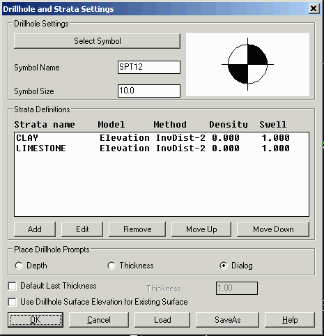
The Strata Definitions in the main dialog need to be in top to
bottom order. To change the order, highlight a strata name and use
the Move Up or Move Down buttons. In this case, we want Clay then
Limestone. Click OK now from the main dialog.
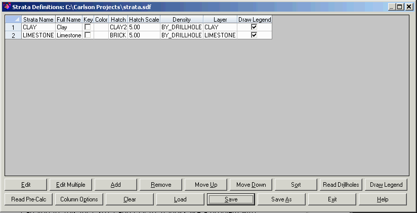
Next run Define Strata/Bed from the
Drillhole menu. Define Strata is used to define the label name,
hatch pattern and color for the strata. Pick Add and fill out the
Strata Definition for Clay as shown and then pick OK.
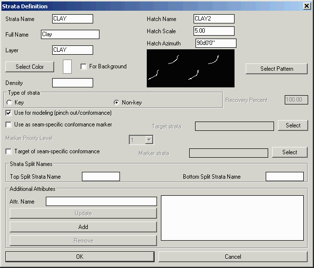
Next, pick the Add button again and fill out the dialog for
Limestone in the same way as Clay except use the Hatch Name of
BRICK. Then pick OK for the Limestone definition. Finally, pick
Save and then Exit from the Strata Definitions dialog.
Step 3 (Input Drillhole Data):
There are two different methods for entering drillhole data into
GeoTech: Drillhole Import and Place Drillhole. Drillhole Import
reads the drillhole data from a text file. This command supports
customizing the sequence of drillhole data fields to match the
format of the text file. Place Drillhole creates the drillholes at
picked positions in the drawing and enters the data in a dialog.
For this tutorial, we will use Drillhole Import.
Run the Drillhole > Import/Export Drillholes > Drillhole
Import command.
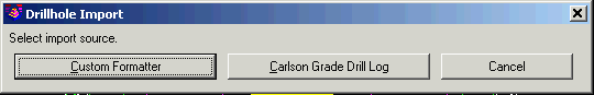
Choose the Custom Formatter button.
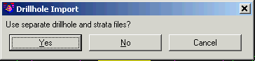
Choose No for Use separate drillhole and strata files. For this
example, both the drillhole and strata data are in the same
file.
For the Drillhole Text File to import, select sample_geotech.csv
from the Carlson Projects folder.

On the Drillhole Import Options dialog, set the options as shown
and then pick OK. Now the drillholes are imported into the
drawing.
The Drillhole Import has brought in the structure for the drillhole
and strata but not the attributes. In this example, there are
strata attributes for moisture and plasticity. Run the Drillhole
> Import/Export Drillholes > Import Qualities
command.
Select Drillholes to update.
Select
objects: all
Select sample_geotech.csv from Carlson Projects for the Quality
Text File.
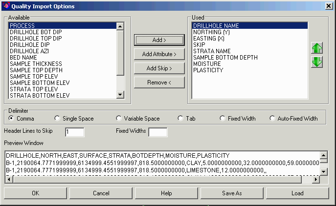
Use the Add, Add Skip and Add Attribute buttons to fill out the
Used list at shown. Then pick OK and the attribute data is added to
the drillholes.
Step 4 (Drillhole Reports):
To setup the project name for the reports, go to Settings >
Drawing Setup and enter in the Project Name and Job Number.
Also set the Horizontal Scale to 100.

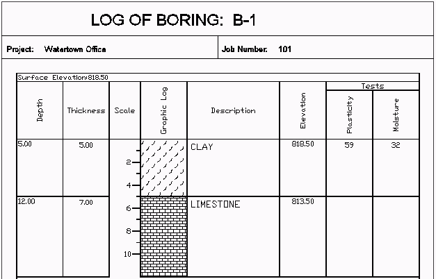
To make log reports pick the Drillhole > Graphic Drillhole
Report command. The program prompts to select drillholes. Type
"all" to report all the drillholes and then the options dialog is
shown.
Select drillholes to report
Select
objects: all
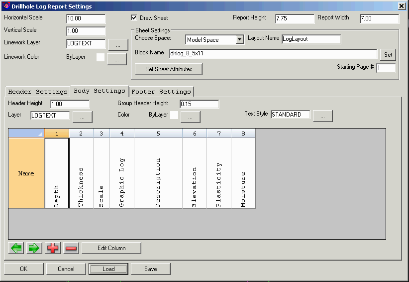
Pick the Load button and select Log2.dhl from the Carlson
Projects\Settings folder. Make sure the dialog has the settings as
shown and then pick OK. Then the program prompts to pick a point
for where to draw the logs. Pick a point in a blank area to the
right of the plan view.
Pick a point to insert log report: pick a
point
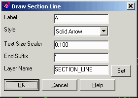
Step 5 (Drillhole Cross Section):
Now let's create a cross section view of the drillholes across the
building pad. First run Draw > Section Line, fill out the dialog
as shown and pick two points across the building pad from left to
right.

Next run StrataCalc > Geologic Column Profile. Set the
Horizontal Scale to 50 and the Vertical Scale to 5 for 10 to 1
exaggeration. Under Drillhole Options, turn on Draw Drillhole Name.
If surfaces are created by Takeoff, then there are options to draw
profiles for existing and design surfaces. When the dialog is
filled out as shown, pick OK on the dialog.

Next the program prompts for the fence polyline. Pick the section
line we just created. The program projects the drillholes onto this
fence polyline that are within the specified max distance to the
polyline. At the command prompt, enter 100 for the max distance.
Then the program prompts for the drillholes to process. Select them
all by entering "all".
Select Fence alignment polyline: pick the section A
line
Maximum drillhole distance from alignment polyline
<100.0>: press Enter
Select Drillholes for geologic column.
Select
objects: all
For the Select Attributes dialog, pick OK without highlighting any
attributes.
At the pick location to draw prompt, pick a point in a blank area
above the plan view.
Pick location for geologic column(s): pick a point in a
blank area
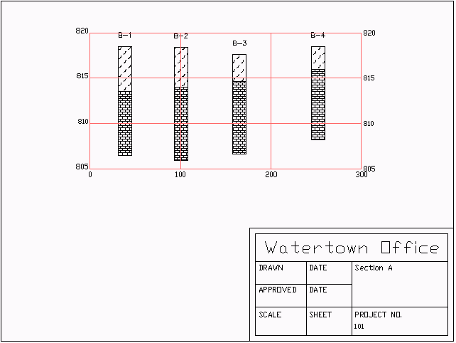
To prepare for plotting, run Map > Title Block. Set the scale to
50 and other settings as shown and pick OK.
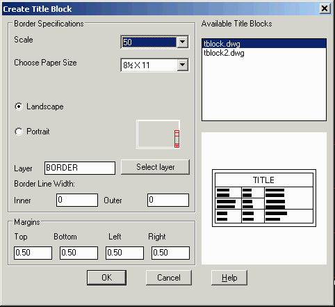
Next pick a point to place the title block that encloses the cross
section grid.
Pick location: pick position for title block
Next there is a dialog for entering attributes for the title
block.
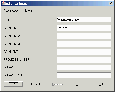
The default title block with the Title Block command is basic. See
the description of the Title Block command for information on how
to customize title blocks. Alternatively, create your own title
block drawing and use the Insert command to place it.
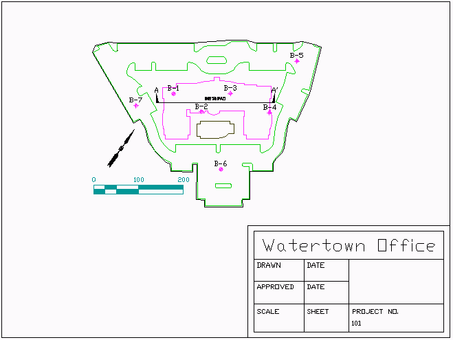
Step 6 (Plan View Map with Drillholes):
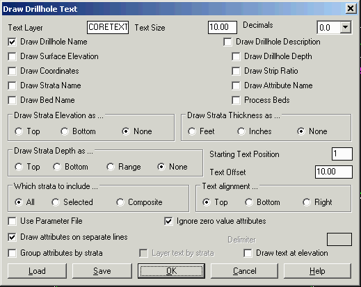
Let's add some annotation to the drawing for the plan view. Run
Drillholes > Label Drillholes > Standard Drillhole
Text. Set the Text Size to 10 and turn on Draw Drillhole Name.
Fill out the dialog as shown and pick OK. Then at the command
prompt, type "all" to select all drillholes to label. For the
Select Attributes dialog, pick OK without highlighting
anything.
Select the Drillholes to label.
Select
objects: all
Next run Map > Bar Scale. Set the Horizontal Scale to 100
and pick OK. Then pick a point in the lower left of the plan view
to place the bar scale.
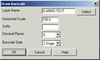
Pick location for barscale: pick a point
Next run Map > North Arrow. Set the dialog as shown and
pick OK. Then pick a point above the bar scale.
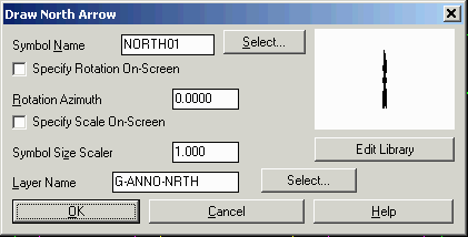
Specify insertion point: pick a point
Finally, run Map > Title Block and use the same settings
as for Step 5 except set the Horizontal Scale to 100 and pick a
point for the title block that encloses the plan view.