The project settings are set by
selecting Settings > Project from the menu, or pressing the SE
icon on the tool bar. The project settings dialog box has six
tabbed windows, Coordinate System, Input Files, Preprocessing,
Adjustment, Standard Errors, and Output Options. Following is an
explanation of the different project settings tabbed
windows.
Notice that there are two buttons at the lower left of the dialog box. The 'Save Project' button can be used to store the current settings to the active project. If there is no active project then the user will be prompted for a new project file name. Projects can also be saved using the 'File/Save Project' menu option from the main menu. The 'Save as Default' button can be used to save the current project settings as the default settings whenever a new project is created. Default project settings can also be defined using the 'File/Save Project as default' menu option from the main menu.
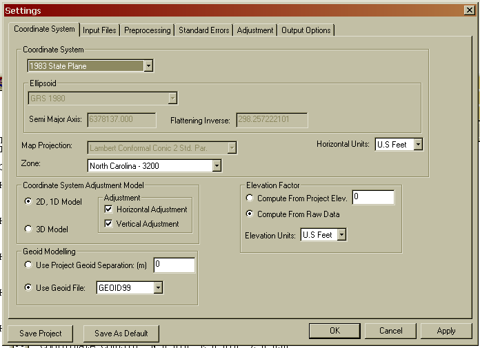
The Coordinate System tab contains settings that relate to the project coordinate system, output units, the adjustment model and other geodetic settings.
You can select either the 3D model or the 2D/1D mathematical model. If you choose 2D/1D mathematical model you can choose to only perform a horizontal adjustment, a vertical adjustment or both. In the 3D model both horizontal and vertical are adjusted simultaneously. The 3D model requires that you choose a geodetic coordinate system. Local, assumed coordinate systems cannot be used with the 3D model. GPS vectors can only be used when using the 3D model.
If using the 2D/1D mathematical model you can select Local (assumed coordinate system), or a geodetic coordinate system such State Plane NAD83, State Plane NAD27, UTM, or a user-defined coordinate system as the coordinate system. When using the 3D model you cannot use a local system.
Select the 'Horizontal Units for' output of coordinate values (Meters, US Feet, or International Feet). In the 3D model both horizontal and vertical units are assumed to be the same. In the 2D/1D model horizontal and vertical units can differ. The 'Horizontal unit' setting in this screen refers to the output units. It is permissible to have input units in feet and output units in meters. Input units are set in the 'Input Files' tabbed screen.
If you choose SPC 1983, SPC 1927, or UTM, the appropriate zone will need to be chosen. The grid scale factor is computed for each measured line using the method described in section 4.2 of NPAA Manual NOS NGS 5, "State Plane Coordinate System of 1983", by James E. Stem.
If using the 2D/1D model and you select a geodetic coordinate system, you have a choice as to how the elevation factor is computed. You can choose to either enter a project elevation or you can choose to have elevations factors computed for each distance based on computed elevations. In order to use the 'Compute Elevation from Raw Data' all HI's and foresight rod heights must be collected for all points.
If you choose a geodetic coordinate system and are using the 2D/1D model you will want to select "Project Elevation" if any of your raw data measurements are missing any rod heights or instrument heights. There must be enough information to compute elevations for all points in order to compute elevation factors. For most survey projects it is sufficient to use an approximate elevation, such as can be obtained from a Quad Sheet for the project elevation.
If you are using either the 3D or the 2D/1D adjustment model using SPC 1983 or UTM reduction you must choose a geoid modeling method. A project geoid separation can be entered or the GEOID99 or GEOID03 grid models can be used. The project must fall within the geographic range of the geoid grid files in order to use GEOID99 or GEOID03 models.
Geoid modeling is used as follows.
Entering a 0.0 value for the separation is the method to use if you
wish to ignore the geoid separation. In the 2D, 1D model it is
assumed that elevations entered as control are entered as
orthometric heights. Since grid reduction requires the data be
reduced to the ellipsoid, the geoid separation is used to compute
ellipsoid elevations. The difference between using geoid modeling
and not using geoid modeling or using a project geoid separation is
insignificant for most surveys of limited extents. In the 3D model
it is also assumed that elevations entered as control are
orthometric heights. Since the adjustment is performed on the
ellipsoid, the geoid separation is used to compute ellipsoid
elevations prior to adjustment. After the adjustment is completed
the adjusted orthometric elevations will be computed from the
adjusted ellipsoid elevations and the computed geoid separation for
each point.
Geoid modeling is especially
important for projects covering large extents. If you incorporate
GPS vector data from an OPUS solution into your project it will be
necessary to use geoid modeling, otherwise your results will be
poor.
If you choose the GEOID99 or GEOID03
modeling option, geoid separations are computed by interpolation
with data points retrieved from geoid separation files. The geoid
separation files should be found in the primary the
installation directory. Grid files have an extension of .grd. These
files should have been installed during the installation of
SurvNet. These files can be downloaded from the Carlson/C&G
website, carlsonsw.com, if needed. The geoid files used by SurvNet
are not in the same format as the geoid files available from NGS.
The geoid files used by SurvNet must come from Carlson/C&G,
either installed during installation or downloaded from the Carlson
website.
If you choose to enter a project geoid separation the best way to determine a project geoid separation is by using the GEOID03 option of the NGS on-line Geodetic Toolkit. Enter a latitude and longitude of the project midpoint and the program will output a project separation.
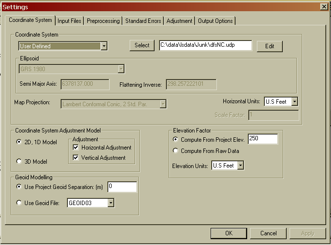
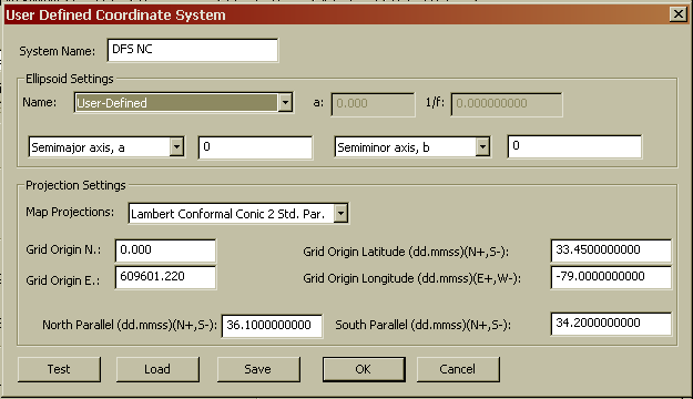
SurvNet allows the creation of
user-defined geodetic coordinate systems (UDP). The ability to
create user-defined coordinate system allows the user to create
geodetic coordinate systems based on projections that are not
explicitly supported by SurvNet. A SurvNet user-defined coordinate
system consists of an ellipsoid, and a map projection,. The
ellipsoid can be one of the explicitly supported ellipsoids or a
user-defined ellipsoid. The supported map projections are
Transverse Mercator, Lambert Conformal Conic with 1 standard
parallel, Lambert Conformal Conic with 2 standard parallels,
Oblique Mercator (NGS), and Double Stereographic projection.
User-defined coordinate systems are created, edited, and attached
to a project from the Project Settings 'Coordinate System' dialog
box. To attach an existing UDP file, *.udp, to a project use the
'Select' button. To edit an existing UDP file or create a new UDP
file use the 'Edit' button.
The User-defined Oblique Mercator
projection used by SurvNet uses the Oblique Mercator projection
formulas published in the NGS document "State Plane Coordinate
System of 1983' by James Stem. This implementation of the Oblique
Mercator projection uses the convention of the False North
and East being the natural origin, as opposed to the origin being
the center of the projection.
The following dialog box is used to create the user-defined coordinate system. The ellipsoid needs to be defined and the appropriate map projection and projection parameters need to be entered. The appropriate parameter fields will be displayed depending on the projection type chosen.
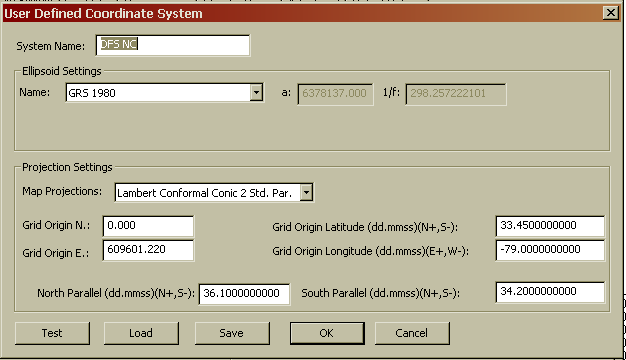
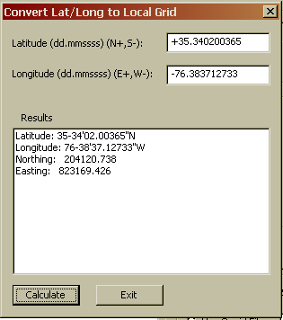
Test - Use the 'Test' button to enter a known latitude and longitude position to check that the UDP is computing correct grid coordinates. Following is the test UDP dialog box. Enter the known lat/long in the top portion of the dialog box then press 'Calculate' and the computed grid coordinates will be displayed in the 'Results' list box.
Load -Use the 'Load' to load the coordinate system parameters from an existing UDP.
Save - Use the 'Save' button to save the displayed UDP. The 'Save' button prompts the user to enter the UDP file name.
OK - Use the 'OK' button to save the UDP using the existing file name and return to the 'Coordinate System' dialog box.
Cancel - Use the 'Cancel' button to
return to the 'Coordinate System' dialog box without saving any
changes to the UDP file.
If you need to define an ellipsoid chose the 'User-Defined'
ellipsoid option. With the user-defined ellipsoid you will then
have the option to enter two of the ellipsoid parameter.
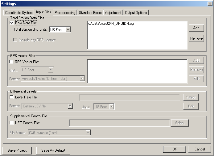
Raw Data Files: Use the 'Add'
button to insert raw total station files into the list. Use the
'Remove' button to remove raw files from the list. All the files in
this list are included in the least squares adjustments. Having the
ability to choose multiple files allows one to keep control in one
file and measurements in another file. Or different files collected
at different times can be processed all at one time. If you have
multiple crews working on the same project using different
equipment, you can have "crew-specific" raw data files with
standard error settings for their particular equipment. Having
separate data files is also a convenient method of working with
large projects. It is often easier to debug and process
individual raw files. Once the individual files are processing
correctly all the files can be included for a final
adjustment.
You can select C&G (.CGR) raw
files, Carlson (.RW5) files or SDMS (.PRJ) files for processing.
You cannot select different file types. For example, you cannot
select both .CGR and .RW5 files in the same project to be processed
at the same time. Notice that you have the ability to highlight
multiple files when removing or adding files
Carlson RW5 files can contain GPS
vector records. If you wish to use the vectors from the RW5 file,
check the "Include any GPS Vectors" box. You can also select RW5
files containing vectors in the GPS vector Files area.
Level Raw Files: Differential
and Trig level files can be entered and processed. There are two
type of level file supported by SurvNET:
.TLV
files - this is the new Carlson level file. It can contain
Trig-Level and/or Differential-Level data. This is the file created
by SurvCE version 2.0 or higher.
.LEV files - this is Carlson's old
level file format. It can contain single-wire or three-wire
differential-level data.
You can view/edit these files by pressing the "Edit" button next to the level file input field.
Under the tools menu pull down, you
have the option to convert level files from other formats to either
a TLV or LEV format.
GPS Vector Files: GPS vector files can be entered and processed. Both GPS vector files and total station raw files can be combined and processed together. You must have chosen the 3D mathematical model in the Coordinate System tab in order to include GPS vectors in the adjustment.
Currently, the following GPS vector file formats are supported.
ASCII (StarNET)
Ashtech / Thales: Thales files typically have .obn extensions and
are binary files.
Carlson RW5 files containing GPS vector records
GeoLab (.IOB)
LandXML, (*.xml)
Leica: Leica files are ASCII files.
NGS G-File
NGS G-File from an OPUS report
StarNet ASCII GPS: See below for more information on StarNet
format. These files typically have .GPS extensions.
Topcon (.tvf): Topcon .tvf files are ASCII files.
Topcon (.xml): Topcon also can output their GPS vectors in XML
format which is in ASCII format.
Trimble Data Exchange Format (.asc): These files are in ASCII
format
Trimble data collection (.dc): These files are ASCII.
Trimble LandXML (.jxl)
The following is a typical vector record in the StarNet ASCII format. GPS vectors typically consist of the 'from' and 'to' point number, the delta X, delta Y, delta Z values from the 'from' and 'to' point, with the XYZ deltas being in the geocentric coordinate system. Additionally the variance/covariance values of the delta XYZ's are included in the vector file.
G0 'V3 00:34 00130015.SSF
G1 400-401 4725.684625 -1175.976652 1127.564218
G2 1.02174748583350E-007 2.19210810829205E-007
1.23924502584092E-007
G3 6.06552466633441E-008 -5.58807795027874E-008
-9.11050726758263E-008
The GO record is a comment. The G1 record includes the 'from' and 'to' point and the delta X, delta Y, and delta Z in the geocentric coordinate system. The G2 record is the variance of X,Y, and Z. The G3 record contains the covariance of XY, the covariance ZX, and the covariance ZY. Most all GPS vector files contain the same data fields in varying formats.
Use the 'Add' button to insert GPS
vector files into the list. Use the 'Delete' button to remove GPS
vector files from the list. All the files in this list will be used
in the least squares adjustments. All the GPS files in the list
must be in the same format. If the GPS file format is ASCII you
have the option to edit the GPS vector files. The Edit option
allows the editing of any of the ASCII GPS files using Notepad.
Typically, only point numbers would be the fields in a GPS vector
file that a user would have need to edit. The variance/covariance
values are used to determine the weights that the GPS vectors will
receive during the adjustment and are not typically edited.
For a variety of reasons it is common
for GPS vector data collected with GPS equipment to have
point names that do not match the point names used in the total
station data. Generally the easiest way to handle this situation is
to first convert the GPS data into the StarNet ASCII .format using
the 'Tools/Convert GPS file to ASCII' menu option. Once the file
has been converted to ASCII it is straightforward to change the G1
records using any text editor to reflect the correct point
numbers.
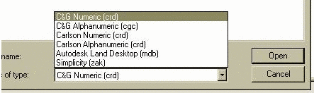
Supplemental Control File: The supplemental control file option allows the user to designate an additional coordinate file to be used as control. The supplemental control files can be from a variety of different file types.
Carlson SQLite
(*.crdb)
C&G numeric (*.crd)
C&G alphanumeric (*.cgc)
Carlson numeric(*.crd)
Carlson alphanumeric(*.crd)
Autodesk Land Desktop (*.mdb)
Simplicity (*.zak)
ASCII P,N,E,Z,D,C (*.nez)
ASCII P,Lat,Long,Ortho,D,C (*.txt)
CSV ASCII NEZ with std. errors
SDMS (.ctl) control file
Note: You should never use the same file for supplemental control points and for final output. Least squares considers all points to be measurements. If the output file is also used as a supplemental control file then after the project has been processed all the points in the project would now be in the control file and all the points in the file would now be considered control points if the project was processed again. The simplest and most straight-forward method to define control for a project is to include the control coordinates in a raw data file.
The Preprocessing tab contains settings that are used in the preprocessing of the raw data.

Compute Traverse Closures: Traditional traverse closures can be computed for both GPS loops and total station traverses. This option has no effect on the computation of final least squares adjusted coordinates. This option is useful for surveyors who due to statutory requirements are still required to compute traditional traverse closures and for those surveyors who still like to view traverse closures prior to the least squares adjustment. This option is used to specify a previously created closure file.
To use this option the user has to first create a traverse closure file. The file contains a .cls extension. The traverse closure file is a file containing an ordered list of the point numbers comprising the traverse. Since the raw data for SurvNet is not expected to be in any particular order it is required that the user most specify the points and the correct order of the points in the traverse loop. Both GPS loops and angle/distance traverses can be defined in a single traverse closure file. More details on creating the traverse closure files follow in a later section of this manual.
Pt. Number Substitution
String: This option is used to automatically renumber point
names based on this string. Some data collectors do not allow the
user to use the same point number twice during data collection. In
least squares it is common to collect measurements to the same
point from different locations. If the data collector does not
allow the collection of data from different points using the same
point number this option can be used to automatically renumber
these points during processing. For example you could enter the
string '=' in the Pt. Number Substitution String. Then if you shot
point 1 but had to call it something else such as 101 you could
enter '=1' in the description field and during preprocessing point
101 would be renumbered as point '1'. With small projects it may be
just as easy to edit the raw data.
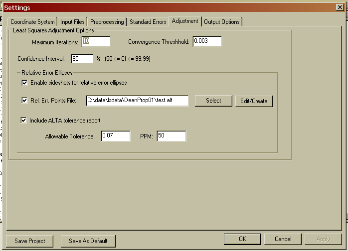
Convergence Threshold: During each iteration corrections are computed. When the corrections are less than the threshold value the solution has converged. This value should be somewhat less than the accuracy of the measurements. For example, if you can only measure distances to the nearest .01' then a reasonable convergence threshold value would be .005'.
Confidence Interval: This setting is used when calculating the size of error ellipses, and in the chi-square testing. For example, a 95% confidence interval means that there is a 95% chance that the error is within the tolerances shown.
Enable sideshots for relative error ellipses: Check this box if you want to see the error ellipses and relative error ellipses of sideshots. This checkbox must be set if you want to use the "relative error ellipse inverse" function with sideshots. When turned off this toggle filters out sideshots during the least squares processing. Since the sideshots are excluded from the least squares processing error ellipses cannot be computed for these points. When this toggle is off, the sideshots are computed after the network has been adjusted. The final coordinate values of the sideshots will be the same regardless of this setting.
Large numbers of sideshots slow down
least squares processing. It is best to uncheck this box while
debugging your project to avoid having to wait for the computer to
finish processing. After the project processes correctly you may
turn on the option for the final processing.
Note: If you wish to get statistics on
certain selected sideshots, you can create an ALT file with the
selected points. This will force them to be included in the
calculation process - even if you have "Enable sideshots for
relative error ellipses" unchecked.
Relative Err. Points File: The ALTA standards require that surveyors certify to the relative positional error between points. Relative error ellipses are an accepted method of determining the relative positional error required by the ALTA standards. The points that are to be included in the relative error checking are specified by the user. These points are defined in an ASCII file with an extension of .alt. To select an .alt file for relative error checking use the 'Select' button and then browse to the file's location.
There is a section later in the manual that describes how to create and edit the .alt file.
Include ALTA tolerance report:
Turn this toggle on if you wish to include the ALTA tolerance
section of the report.
Allowable Tolerance, PPM: These fields allow the user to set the
allowable error for computations. Typically the user would enter
the current ALTA error standards, i.e. 0.07' & 50 PPM.
See the later section in this manual for more detailed information on creating and interpreting the ALTA section of the report.
Standard Errors
Standard errors are the expected
measurement errors based on the type equipment and field procedures
being used. For example, if you are using a 5 second total station,
you would expect the angles to be measured within +/- 5 seconds
(Reading error).
The Distance Constant, PPM settings, and Angle Reading should be
based on the equipment and field procedures being used. These
values can be obtained from the published specifications for the
total station. Or the distance PPM and constant can be computed for
a specific EDM by performing an EDM calibration using an EDM
calibration baseline.
Survey methods should also be taken into account when setting standard errors. For example, you might set the target centering standard error higher when you are sighting a held prism pole than you would if you were sighting a prism set on a tripod.
The settings from this dialog box will be used for the project default settings. These default standard errors can be overridden for specific measurements by placing SE records directly into the Raw Data File (see the above section on raw data files).
If the report generated when you process the data shows that generally you have consistently high standard residuals for a particular measurement value (angles, distances, etc.), then there is the chance that you have selected standard errors that are better than your instrument and methods can obtain. (See explanation of report file). Failing the chi-square test consistently is also an indication that the selected standard errors are not consistent with the field measurements.
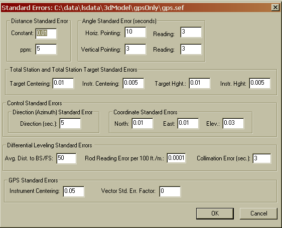
You can set the standard errors for the following:
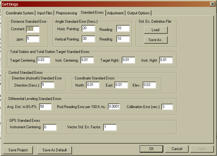
Distance and Angle Standard Errors
Distance Constant: Constant portion of the distance error. This value can be obtained from published EDM specifications, or from an EDM calibration.
Distance PPM: Parts per million component of the distance error. This value can be obtained from published EDM specification, or from an EDM calibration.
Horizontal Angle Pointing: The horizontal angle pointing error is influenced by atmospheric conditions, optics, experience and care taken by instrument operator.
Horizontal Angle Reading: Precision of horizontal angle measurements, obtain from theodolite specs.
Vertical Angle Pointing: The vertical angle pointing error is influenced by atmospheric conditions, optics, experience and care taken by instrument operator.
Vertical Angle Reading: Precision of vertical angle measurements, obtain from theodolite specs.
Instrument and Target Standard Errors
Target Centering: This value is the expected amount of error in setting the target or prism over the point.
Instrument Centering: The expected amount of error in setting the total station over the point.
Target Height: The expected amount of error in measuring the height of the target.
Instrument Height: The expected amount of error in measuring the height of the total station.
Control Standard Errors
Direction (Bearing / Azimuth): The
estimated amount of error in the bearing / azimuth (direction)
found in the azimuth records of the raw data.
North, East, Elev: The estimated amount of error in the
control north, east and elev. You may want to have different
coordinate standard errors for different methods of obtaining
control. Control derived from RTK GPS would be higher than control
derived from GPS static measurements.
GPS Standard Errors
Instrument Centering: This option is used to specify the error associated with centering a GPS receiver over a point.
Vector Standard Error Factor: This
option is used as a factor to increase GPS vector standard errors
as found in the input GPS vector file. Some people think that the
GPS vector variances/covariances as found in GPS vector files tend
to be overly optimistic. This factor allows the user to globally
increase the GPS vector standard errors without having to edit the
GPS vector file. A factor of 0 should be the default value and
results in no change to the GPS vector standard errors as found in
the GPS vector file. The maximum value allowed is 10.
Differential Leveling Standard Errors
These setting only effect level data and are not used when processing total station or GPS vector files.
Avg, Dist. To BS/FS: This option is used to define the average distance to the backsight and foresight during leveling.
Rod Reading Error per 100 ft./m: This option is used to define the expected level reading error.
Collimation Error: This is the expected differential leveling collimation error in seconds.
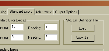
Standard Error Definition Files
The Standard error settings can be saved and then later reloaded into an existing or new project. Creating libraries of standard errors for different types of survey equipment or survey procedures is convenient method of creating standards within a survey department that uses a variety of equipment and performs different types of surveys. Standard error library files, *.sef files, can be created two ways. From the 'Settings/Standard Errors' dialog box the 'Load' button can be used to import an existing .sef file into the current project. A .sef file can also be created from the existing project standard errors by using the 'Save As..' button.
Standard error files, .sef files, can also be managed from the main 'Files' menu. Use the 'Edit Standard Error File' menu option to edit an existing standard error file. Use the 'New Standard Error File' option to create a new standard error file.
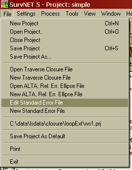
After choosing one of the menu options and choosing the file to edit or create, the following dialog box will be shown. Set the desired standard errors and press the 'OK' button to save the standard error file.
These settings apply to the output of data to the report and coordinate files.
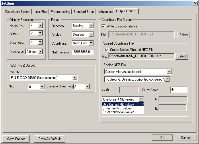
These settings determine
the number of decimal places to display in the reports for the
following types of data. The display precision has no effect on any
computations, only the display of the
reports.
Coordinates (North, East, Elevation)
- Chose 0-4 decimal places.
Distances - Chose 0-4 decimal places
Directions (Azimuths or Bearings) - nearest second, tenth of
second, or hundredth of second.
These settings determine the format for the following types of data.
Direction - Choose either
bearings or azimuth for direction display. If the angle units are
degrees, bearings are entered as QDD.MMSSss and azimuths are
entered as DDD.MMSSss. If the angle units are grads, bearings are
input as QGGG.ggggg and azimuths are input as GGG.ggggg.
Coordinate Display - Choose the order of coordinate display, either north-east or east-north.
Null Elevation - Choose the value for null elevations in the output ASCII coordinate NEZ file. The Null Elevation field defaults to SurvNet’s value for NO ELEVATION,of -999999999.0 .
Angle Display - Choose the units you are working int, degrees or gradians.
These settings determine the type and format of the output NEZ file. An ASCII .NEZ and .OUT files are always created after processing the raw data. The .OUT file will be a nicely formatted version of the .NEZ file suitable for printing. The .NEZ file will be an ASCII file suitable to be input into other programs. There are a variety of options for the format of the .NEZ file. Following are the different ASCII file output options.
P,N,E,Z,CD,DESC (fixed columns); - Point,north,east,elev.,code,desc in fixed columns separated by commas.
P,N,E,Z,CD,DESC; Point,north,east,elev.,code,desc separated by commas.
P N E Z CD DESC (fixed columns); Point,north,east,elev.,code,desc in fixed columns with no commas.
P N E Z CD DESC; Point,north,east,elev.,code,desc in fixed columns with no commas.
P,N,E,Z,DESC (fixed columns); Point,north,east,elev., desc in fixed columns separated by commas.
P,N,E,Z,DESC; Point,north,east,elev., desc separated by commas.
P N E Z DESC (fixed columns); Point,north,east,elev., desc in fixed columns with no commas.
P N E Z DESC; Point,north,east,elev.,code,desc separated by spaces.
P,E,N,Z,CD,DESC (fixed columns); - Point,east,north,elev.,code,desc in fixed columns separated by commas.
P,E,N,Z,CD,DESC; Point,east,north,elev.,code,desc separated by commas.
P E N Z CD DESC (fixed columns); Point,east,north,elev.,code,desc in fixed columns with no commas.
P E N Z CD DESC; Point,east,north,elev.,code,desc in fixed columns with no commas.
P,E,N,Z,DESC (fixed columns); Point,east,north,elev., desc in fixed columns separated by commas.
P,E,N,Z,DESC; Point,east,north,elev., desc separated by commas.
P E N Z DESC (fixed columns); Point,east,,northelev., desc in fixed columns with no commas.
P E N Z DESC;
Point,east,north,elev.,code,desc separated by spaces.
CSV ASCII with std. errors (This
format is useful as it can be used as a supplemental control input
file type option, where the coordinate standard errors output for
one project can be used as input for another project.)
* N/E Precision: number of places after the decimal to use for North and East values (0 -> 8) in the output NEZ ASCII file.
* Elevation Precision: number
of places after the decimal to use for Elevation values (0 -> 8)
in the output NEZ ASCII file.
If you want to write the calculated
coordinates directly to a Carlson or C&G coordinate file, check
the "Write to Coordinate File" box and select the file. You can
choose the type of Carlson/C&G file to be created when you
'select' the file to be created. You may wish to leave this box
unchecked until you are satisfied with the adjustment. Following
are the different available coordinate output file options.
* NOTE: If coordinate points already exist in the CRD file, and
they have different values, before a point is written, you will be
shown the NEW value, the OLD value, and given the following
option:
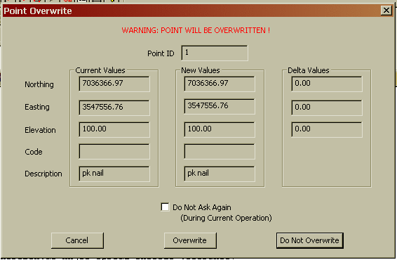
Cancel: Cancel the present operation. No more points will be written to the Carson/C&G file.
Overwrite: Overwrite the existing point. Notice that if you check the 'Do Not Ask Again' box all further duplicate points will be overwritten without prompting.
Do not Overwrite: The existing
point will not be overwritten. Notice that if you check the 'Do Not
Ask Again' box all further duplicate points will automatically not
be overwritten - only new points will be written.
This feature allows you to output to
a second, "Scaled" coordinate file. The main purpose of this
feature is to create a GROUND based coordinate file when working on
a SPC system.
First check the "Create Scaled/Ground
NEZ File" checkbox to turn the feature ON.
Select the TYPE coordinate file you
wish to output to and select the file.
If your project is based on a SPC
system, you will have the following scaling options:
To
Ground. Use avg. computed combined SF
Manually enter SF
If you select the first option, the
combined scale factor is calculated for each of the points and then
the total is averaged. The inverse of this scale factor will be
used to calculate the coordinates of the SCALED coordinate
file. This will give you GROUND coordinates for the
project.
If you wish, you may also manually
enter the desired scale factor.
If your project is based on a Local
or Assumed coordinate system, you will only have the option to
manually enter the scale factor as the scale factors cannot be
calculated.
Next you will enter the point number
you wish to SCALE around:
Pt.
to Scale
Next you have the following
TRANSLATION options:
Use
current NE values
Enter new NE values
Enter translation values
The first option will use the current coordinates of the SCALE POINT, all other coordinate points will be scaled around this point.
The second option allows you to enter
NEW coordinate values for the SCALE POINT. All the points will
first be translated so that the SCALE POINT has the values entered
here and then they will be scaled around the SCALE POINT.
The third option allows you to
directly enter the delta-north and delta-east translation values.
All the points will first be translated and then scaled.
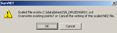 If you
pick OK the points in the Scaled File will be overwritten. If you
Cancel no point will be written to the Scaled File.
If you
pick OK the points in the Scaled File will be overwritten. If you
Cancel no point will be written to the Scaled File.