Legal Description Writer Dialog
This initial and primary dialog box is shown above, and described below.
The Legal Description Writer gives you the ability to
create a detailed legal description from a polyline. This
description consists of calculated calls, point descriptions from
Carlson points, and numerous user defined terms. The programs
values for these terms are easily replaced, and are stored as
defaults with each use. When a scale factor is specified under
Drawing Setup, the Legal Description distances will apply the scale
factor which is a way to report grid distances from ground drawing
coordinates or vice versa.
In addition to this command, you can also generate legal
descriptions by point numbers with the Report function within the
Lot File Manager command.
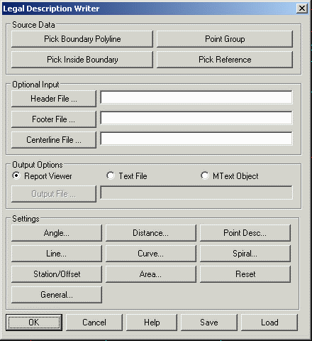
Legal Description Writer Dialog
This initial and primary
dialog box is shown above, and described below.
Pick Boundary Polyline: This button is used to designate
the polyline boundary used. The boundary should be a closed
polyline. Tools are provided in the Edit menu if you need to
reverse the polyline or change its origin point. You can also
select multiple polylines to process at the same time by entering M
for Multiple at the Select Boundary Polyline prompt in this
routine.
Pick Inside Boundary: This button is another way to
designate the polyline boundary. With this method, the boundary can
be defined by multiple linework entities. You pick inside the
boundary area and the program will figure the boundary perimeter
from the surrounding linework. This method uses the same technique
as the Draw->Boundary Polyline command. The boundary perimeter
that the program finds is highlighted for visual
confirmation.
Pick Reference Lines: Used to select lines that tie into
the polyline boundary used for the legal description. These should
be LINE objects that have one endpoint exactly the same as the
beginning point of the boundary polyline. If a Carlson point exists
at the end of the line away from the boundary, the routine will
pick up its description, otherwise you will be prompted for the
description. You can choose any number of reference lines, simply
press enter to conclude the selection of reference lines.
Point Group: This method defines the perimeter by a
series of points from a group defined by the Point Group Manager
command. In Point Group Manager, a group can be defined as a point
list including the ability to have radius points.
Header File: This button and edit field are used to designate the optional header text file. If a valid file is selected it will be written into the top of the output.
Footer File: This button and edit field are used to designate the optional footer text file. If a file is selected it will be written at the end of the output.
Centerline File: This allows you to set an optional
reference centerline for reporting station/offset for each point in
the boundary.
Output Options allows you to select where Legal Description Writer should send the output.
Report Viewer: The output is sent to the report viewer
specified under Configure Carlson->General settings: Carlson
Standard Report Viewer, Windows Notepad or Microsoft Word.

Text File: The output is sent to an external text file as designated in the output file section described below.
Mtext Object: This creates a mtext object in the current drawing. Upon choosing OK you will be prompted for a starting point (which is the upper left corner) and well as a second point that determines the width and angle. By default ortho is turned on for this second point. Press the F8 key to toggle its status.
Output File: This button and edit field are used to
designate the necessary output text file. This file can then be
brought into your word processor and finalized. Note that the
appearance of the output file can be affected by the status of the
'Use Paragraph Format' toggle in the Legal Description's General
settings.
 Bearing Format: Designate the character or
word used in each bearing direction. Standard values are the
letters N, S, E, or W. One possible option is the entire words
NORTH, SOUTH, EAST, and WEST. It is important to keep in mind that
spaces are literal, meaning that if you don't have a literal space
after N/S, and before E/W, a space will not be formatted into the
bearing. To use Azimuth, place a check in the Use Azimuth box and
the General Prefix will be set to AZ.
Bearing Format: Designate the character or
word used in each bearing direction. Standard values are the
letters N, S, E, or W. One possible option is the entire words
NORTH, SOUTH, EAST, and WEST. It is important to keep in mind that
spaces are literal, meaning that if you don't have a literal space
after N/S, and before E/W, a space will not be formatted into the
bearing. To use Azimuth, place a check in the Use Azimuth box and
the General Prefix will be set to AZ.
1-Words Quads: For example bearings that are due NORTH, the default is to generate N 00_ 00' 00 E. If the 1-Word Quads toggle is turned on, the program will substitute the single word (which you can change) for the direction, these usually being NORTH, or DUE NORTH.
Symbols: This section allows you to designate the precision for bearings, as well as the symbols used. Turn on/off the toggles for degrees, minutes, and seconds to control the precision. For example, if you wish to round to the nearest minute, simply clear the toggle from the second field. For each field (degrees, minutes, seconds), you can supply the character or word to be used. You can quickly fill in these fields with the two buttons to the right.
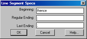
Line Segment Specifications
This section is used to establish the terms used when the course of
a call is a line segment, as is often the case. Simply supply the
beginning and ending terms for these line calls.
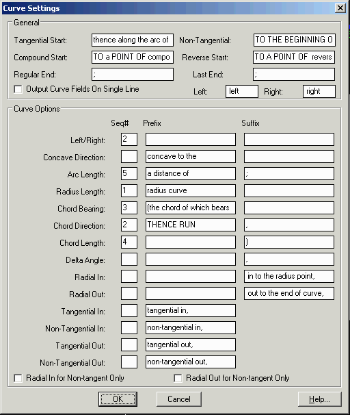
Curve Segment
Specifications
This large dialog is used to establish the terms and options used
when creating the course of a curve. Basic options include
beginning and ending terms, as well as the words for left and right
if chosen. In the large table of curve options, you can choose the
items you wish to report, in the order you want them to appear.
Simply place a number in the sequence field indicating the items
you wish to report, making sure that there are no duplicate
numbers. In the example below, the program would output the curve
direction, arc length, radius length, chord bearing, and chord
length, radius length, chord bearing, and chord length, and in that
order. Each field can also have a unique prefix/suffix. There are
four different possible phrases for the start of the curve
description for whether the curve is tangential, non-tangential,
compound or reverse. The Radial In/Out for Non-tangent Only option
applies to the Radial In/Out fields and tell the program to only
use these fields when the curve is non-tangent. Otherwise, these
fields are always used when the Radial In/Out fields are in the
sequence.
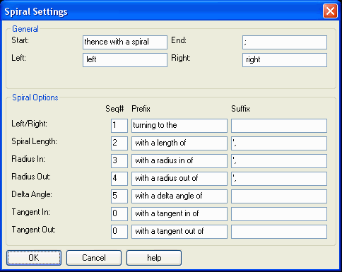
Spiral Specifications
This subdialog has the setting for reporting spiral portions of the
boundary. In order to pick up the spiral, a centerline (.CL)
containing the spiral must be drawn using the Draw Centerline File
command. Then the program will pick up the spiral definition for
any portion of the legal description boundary that follows the
spiral on the centerline.
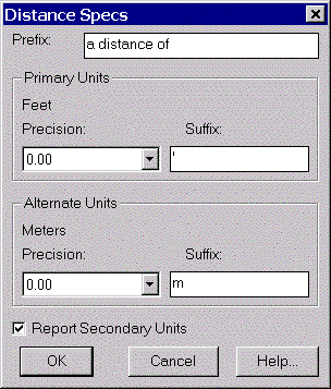
Distance Specifications
This subdialog is used to establish the terms and precision used
when creating a distance for the course of a call. The precision
and suffix apply to curves as well. Simply choose the desired
distance precision from the popdown, and supply the beginning and
ending terms for the line calls.
Note the availability of dual distance
reporting. If you would like to report dual distances such as
feet/metric, turn on the toggle in the lower left corner of the
dialog. Note that the primary units are the units set in the
Settings menu, Drawing Setup. If you have English set as your units
in Drawing Setup, then the alternate units will be metric. The
opposite also applies. If your units in Drawing Setup is set to
metric, then the alternate units will be English.
Description Specifications
In the process of following the polyline definition for a boundary,
the legal description writer can look for descriptions of the
points at the endpoints of the polyline. These can be extracted by
setting the data source to the corresponding point from the
coordinate (.CRD) file, meaning the points do not have to be
plotted on the screen. A second option is point block, in which the
program will read the information from the drawing, and not require
the presence of a coordinate (.CRD) file.
 Prefix: General term applied before the
actual description.
Prefix: General term applied before the
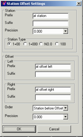
actual description.Station/Offset
Specifications
When using a reference centerline file, the report will include the
station and offset for each of the points in the boundary. The
settings in this dialog control the format of these values.
General Specifications
This dialog controls general specifications which can affect the
entire description. Each group of items are explained in detail
below.
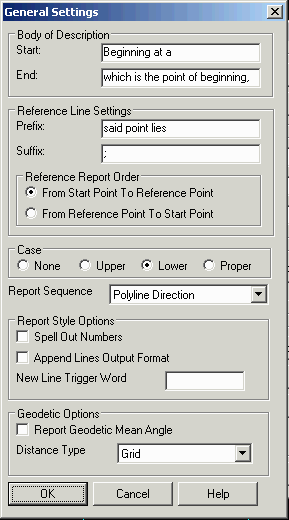
Body of Description: Enter the beginning and ending terms for the description.
String Case: Choose the button
corresponding to the string case conversion desired. If you want no
changes made, choose none. Choosing upper, lower, or proper case
conversion will affect the case of all text throughout the
description, except bearing letters.
Report Sequence: This option controls the sequence to report
the boundary segments either in the direction of the polyline,
clockwise or counter-clockwise.
Spell Out Numbers: This option writes numbers as words instead of digits. For example, a distance of 123 would be written as one hundred twenty three.
Append Lines Output Format: If
this toggle is on, the program will output the description without
carriage returns after each line. This approach makes a nice
paragraph style when brought into a word processor with word wrap.
If the toggle is cleared, the program will place carriage returns
at the end of each call.
Geodetic Options: In order to use these options, the grid projection for the drawing must be set using the Settings > Drawing Setup command. The Report Geodetic Mean Angle option reports the geodetic mean angle which is the average of the geodetic bearings at the two point instead of reporting the direct coordinate bearing between two points. Distance Type controls whether to report grid distances or geodetic distances at zero or mean elevation.
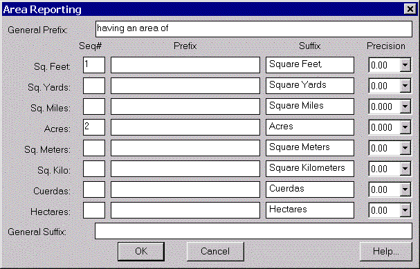
Area Specifications
The legal description writer can output several types of areas.
Basic options include beginning and ending terms. In the large
table of area options, you can choose the items you wish to report,
in the order you want them to appear. Simply place a number in the
sequence field indicating the items you wish to report, making sure
that there are no duplicate numbers. You can edit the prefix/suffix
for each and control decimal precision of each field
output.
Reset: This option will reset all settings to their original default values.
Save: This option saves the legal
description settings to a file. The file will be saved with
an extension of (LGL).
Load: This option loads previously
saved legal description (*.LGL) files.
Pulldown Menu Location:
Survey
Keyboard Command: legal
Prerequisite: Polyline boundary