
The Bearing-Distance Intersect command prompts the user for a
base point from which the known bearing intersects. It then defines
the bearing by one of three methods. The bearing can be defined by
picking two points, selecting a line with the same bearing or by
typing in the bearing in the form of Qdd.mmss (similar to the
Locate by Bearing command). Next the user is prompted for a
base point from which the known distance radiates. After entering
the known distance a circle is drawn radiating from the selected
base point, and a line defined by the bearing is extended to
intersect the circle. The user then picks the correct point for the
solution desired and a point symbol is located at the selected
intersection. The command then erases the temporary circle and
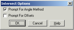
line. The Options choice allows you to be prompted for angle method
or for offsets, or both.
When a grid projection for the drawing is defined under Drawing
Setup, this command will prompt for whether to use the grid bearing
or geodetic mean, forward or back bearing. Also, the program will
prompt for whether to use the grid or geodetic distance.
[Enter] to use preview point or select known Bearing base
point
Options/Pick point or point number: pick point
Define 1st bearing by
(Line/Points/Azimuth/Bearing)<Bearing>: l
Select Line or Polyline that
Defines Bearing: pick entity
Enter 1st Offset Distance
<0.0>: press Enter
Known distance base point.
Pick point or point number: pick point
Points/<Enter
Distance>: 40.41
Enter 2nd Offset Distance
<0.0>: press Enter
[int on] Pick Intersection point ([Enter] to cancel):
pick point
Enter Point Number <55>: press Enter This prompt appears only if
Automatic Point Numbering is turned off. See Point Defaults
Enter Point Symbol Number <4>: press
Enter This prompt appears only if point symbol prompting is
turned on. Symbol number 4 is located at the computed coordinate
and labeled point number 55.
|
| When Options (O) is selected |
Pulldown Menu Location: COGO > Locate at Intersect
Keyboard Command: bdint
Prerequisite: None