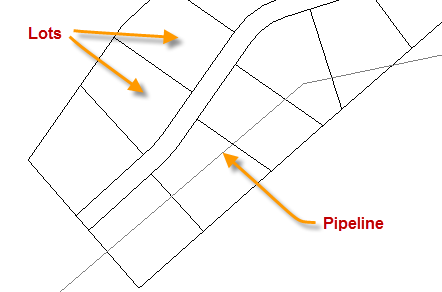
This command will create a table using user selected information and user defined table features. A polyline is selected that crosses one or more lots. Lots must be defined in a Lot file prior to running the command. In the following example the polyline is labeled as a Pipeline.
When the command is started the user is presented with the Lot Crossing Settings dialog box. There two tabs; Label Fields and Settings and Table Settings.
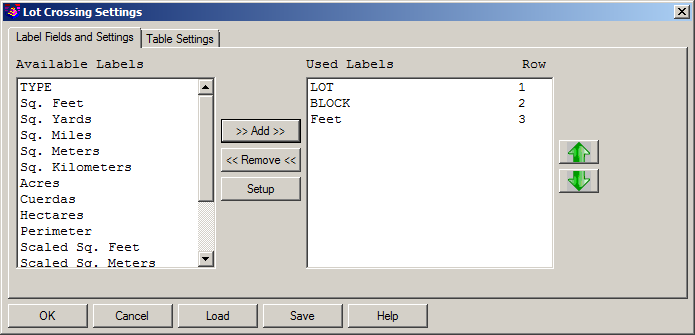
Available Labels: This is the list of information that may be included in the table.
Used Labels: These are the items that have been selected to be in the table. They are placed in the table in the order listed. The green up and down arrows will move used labels up or down in the list.
Add: Clicking the Add button will add the highlighted labels in the available list to the used list.
Remove: Clicking the Remove button will remove labels highlighted in the used list and display in the available list.
Setup: Setup opens the Field Settings dialog for the Used Label that is highlighted.
OK: Clicking the OK button will proceed to the selection of the crossing polyline.
Cancel: ends the command with no table being created.
Load: Loads previously saved settings so table created match previous tables.
Save: Saves the settings as currently displayed for use on future tables.
Help: Load this file.
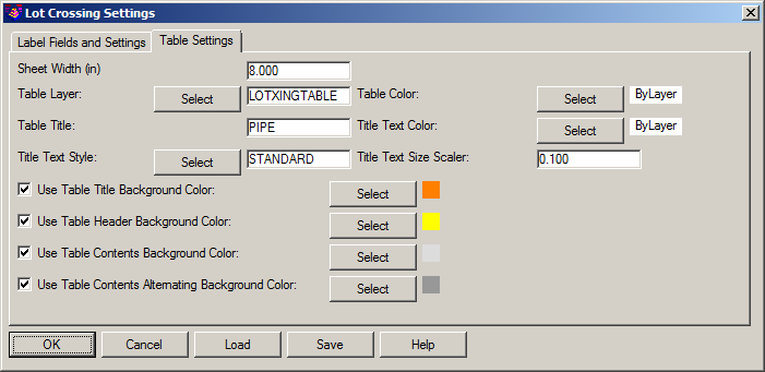
Sheet Width (in): This value defines the width of the table. If set too small the text in the table will overlap.
Table Layer: Select an existing layer to draw the table on using the Select button or use a new layer by typing the name in the edit field.
Table Color: The use can specify a color for the table gridlines using the Select button. Bylayer will use the color assigned to the Table Layer for the grid lines.
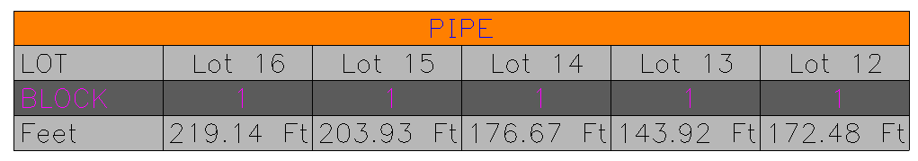
Table Title: A title can be specified for the table by typing the desired title in the Table Title field. See example below.
Title Text Color: This specifies the color for the Table Title text.
Title Text Style: This specifies the text style for the Table Title text. Be sure the style specified is defined in your drawing.
Title Text Size Scaler: This specifies the plotted height of the Table Title text. The table is drawn in model space. The height of the text in model space is the Text Size Scaler multiplied by the horizontal scale in Drawing Setup.
Use Table Tile Background Color: This option allows the user to specify a background color for the Table Title.
Use Table Header Background Color: This option allow the user to specify a background color for the Table Header row.
Use Table Contents Background Color: This option allows the user to specify a background color for body of the table.
Use Table Contents Alternating Background Color: If the Table Contents Background color is being used, This option allows the user to specify a second color to use on alternating rows of the table body.
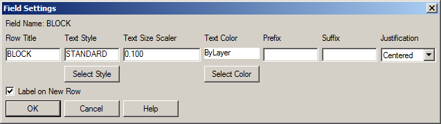
The Field Settings dialog box is opened by double-clicking a Used Label or highlighting a Used Labels and clicking the Setup button.
Row Title: Row Titles are the Used Labels that were selected Label Fields and Settings tab.
Text Style: This specifies the text style to be used for the current row text. You may use the Select button to choose a text style. Be sure the selected text style is loaded in the drawing.
Text Style Scaler: This specifies the plotted height of the current row text. The table is drawn in model space. The height of the text in model space is the Text Size Scaler multiplied by the horizontal scale in Drawing Setup.
Text Color: This specifies the color for the current row text. You can use the Select Color button to choose the color from a pallet. Bylayer uses the color of the Table layer for the text.
Prefix: This places the user provided prefix text with the row entries. An example would be prefixing lot numbers with the word Lot.
Suffix: This places the user provided suffix text with the row entries. An example would be using ft for feet as a suffix for a length.
Justification: Users can specify, Left, Center or Right text justification.
Table numeric values that are calculated, like area or lengths, have the two following controls in addition to those listed above.
+/-: Users may specify a +/- be used as a prefix or suffix. The default is None, not used.
Precision: Decimal precision for calculated numeric values can be set to zero and up eight decimal places.
OK: Saves changes and closed the Field Setting dialog box.
Cancel: Closes the Field Settings dialog box without saving changes.
Help: Accesses this documentation.
Pick a polyline for lot crossings: Select polyline crossing lots
Starting Station <0.0 >: Enter desired starting station
Ending Station <1642.88> Accept full length or enter ending station to process a part of the polyline.
Pick location for report table: Select location in drawing for table
Pulldown Menu Location(s):
Survey Module: Area/Layout > Lot File
Utilities > Right of Way Crossings Table
Keyboard Command: lotcross
Prerequisite: Polyline and Lot File