This command combines input, edit, draw and report lot
capabilities into one command.
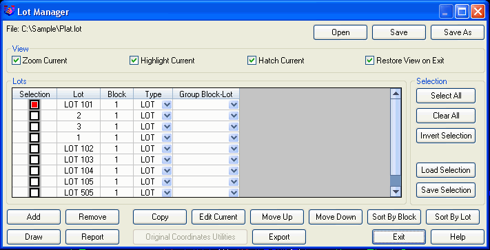
Main Dialog
In the main dialog, there is a spreadsheet list for the lot names
along with the block name, lot type and group assignment for each
lot. You can edit these values directly in the spreadsheet. There
are also function buttons as follows:
Open: selects another Lot
File to process.
Save: saves the lot data to
the current lot file.
SaveAs: prompts for another
file name to save the lot data to.
View: The View options
control drawing effects when you highlight lots in the spreadsheet
list.
Zoom Current: zooms the
display view to include the selected lot.
Highlight Current:
highlights the perimeter of the selected lot as a dashed line.
Hatch Current: fills in the
selected lot with a hatch.
Restore View on Exit: on
leaving Lot Manager, this option sets the display to the original
position before running Lot Manager.
Lot Selection: Many of the
functions such as Draw process only the lots that are in selected
mode. You can toggle which lots are selected with the buttons in
the Selection spreadsheet column. You can also use the buttons in
the Selection section to select the lots to process.
Select All: marks all the
lots as selected.
Clear All: unselects all
the lots.
Invert Selection: flips
currently selected lots to unselected status and currently
unselected to selected status.
Load Selection: sets the
current selection status from a .LSS file.
Save Selection: saves the
current selection status to a .LSS file.
Add: creates a new lot. The
new lot name is automatically generated by incrementing from the
highest lot name.
Remove: deletes the
currently selected lots.
Copy: creates new lots as
copies of the currently selected lots.
Edit Current: brings up a
dialog editor for the highlighted lot (see below).
Move Up/Down: changes the
order of the highlighted lot in the list.
Sort By Block: sorts the
lots by block name order first and then by lot name within each
block.
Sort By Lot: sorts the lots
by lot name only without using the block name.
Clockwise Order: sets the order for the lot points for the
selected lots as either clockwise or counter-clockwise.
Point Group: creates a point group for the lot points of the
selected lots.
Draw: draws the selected
lot perimeters and annotation (see below).
Report: reports the
selected lots (see below).
Original Coordinates
Utilities: has methods for tracking lot coordinate
transformations of the current coordinates relative to the original
coordinates.
Export: output selected
lots to a new lot file as a way to make a subset lot file.
Edit
This dialog allows you to edit the lot name, block name, group,
coordinate file, starting station, ending station and the point
numbers that define the lot. A curve is specified by the PC, radius
point and PT point numbers. The Large Arc option indicates a curve
with an included angle greater than 180 degrees. The Select button
allows you to specify a new name or location for the coordinate
file associated with the lot.
Add: adds a new point to
the lot.
Remove: removes the
highlighted point from the lot.
Move Up/Down: changes the
order of the highlighted point in the list.
Reverse: reverses the order
of the points.
Set POB: sets the point of
beginning, starting point, to the currently highlighted
point.

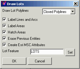
Draw
The Draw routine allows you to draw polylines for the lot
perimeters as well as annotate the lot linework and areas.
Draw Lot Polylines: The
Closed Polylines method creates a closed polyline for each lot. The
Lines and Arcs method draws the sides of the lots as a series of
lines and arcs. The advantage of the Closed Polylines method is
that each lot is completely defined by the closed polyline. The
advantage of the Lines and Arcs method is that there are no
overlapping entities for common borders between lots. With the
Lines and Arcs method, the program draws the common border entities
only once. The layer for the polylines is set by the Lot Type which
is defined in Define Lot Attributes. If the Lot Type is not
defined, then the polyline are drawn in the current layer.
Label Lines and Arcs:
Labels the bearing, distance, and curve data using the
Auto-Annotate command. See
Auto-Annotate for more
details.
Label Areas: Labels the area, and optionally the name of the
selected lots using the Area Settings dialog. See
Area
Defaults for more details.
Hatch Areas: Hatches the lot areas.
Create Esri MSC Attributes: Defines an Esri MSC format lot
feature in the drawing with the lot attributes.
Erase Previous Entities:
Erases lot polylines and labels from earlier runs of Draw to avoid
duplicates.
Report
The Report routine has several types of reports.
Report Areas Only: When checked only the lot name, block
name, and area are included in the report.
Report Stations: Controls
whether to report the distance along the lot perimeter.
Report Elevations: Controls
whether to report the elevation from the coordinate file for each
lot point.
Report Point Descriptions:
Controls whether to report the description from the coordinate file
for each lot point.
Report Station/Offset To Reference CL: This option prompts for
a CL file that is used to calculate stations and offsets for each
of the lot points to include in the report.
Add Page Break between Lots: Formats the report so that each
lot definition begins on a new page when printed.
Use Report Formatter: When checked, the report is output to
the Report Formatter where it can be customized as well as
exported to Microsoft® Excel or Microsoft® Access. See Report
Formatter in for more details.
Report Closure By: If the Start/End Coordinates method is
used, closure error distance is typically 0 (perfect closure—you
end where you start). If the Angle/Distance Precision method is
used, then the actual bearings and distances (computed from the
coordinates) in the report are used, and due to the rounding used
to present the bearings and distances, minute closure errors will
occur which will be reported.
Report Precision: Specify the decimal precision for
reporting coordinates, distance and angles on the report. The
precision for the areas is defined in the Area Defaults
command.
Unequal Radius Tolerance: When reporting the curve data for
a lot, the two radial lengths are compared. If the difference in
their length is more than this value, it is noted on the
report.
Check Lot Report: Checks
that the area for all the lots assigned to a Group Block-Lot add up
to the area of the area of the enclosing group lot.
Lot Report: Creates a
report using the report settings.
Legal Description Report:
Writes a legal description using the same routine as the Legal
Description Writer command. See the Legal Description Writer
section of the manual for more details.
 Lot Report
Lot File: C:\sample\CivilDemo.lot

CRD File: C:\sample\CivilDemo.crd


LOT 55           OF BLOCK 1, TYPE: LOT

PNT#   Bearing          Distance  Northing     Easting      Station

36                                3374.827     4631.668     0.000

  Radius: 642.845   Length: 85.660    Chord: 85.597    Delta: 07°38'05"

  Chord BRG: S 60°07'05" W  Rad-In: N 33°41'58" W  Rad-Out: N 26°03'53" W

  Radius Pt: 8 3909.649,4274.994  Tangent: 42.894 Dir: Right

  Tangent-In: S 56°18'02" W  Tangent-Out: S 63°56'07" W

  Non Tangential-Out

41                                3332.181     4557.451     85.660

       N 26°03'53" W    175.000

42                                3489.384     4480.558     260.660

  Radius: 467.845   Length: 62.341    Chord: 62.295    Delta: 07°38'05"

  Chord BRG: N 60°07'05" E  Rad-In: N 26°03'53" W  Rad-Out: N 33°41'58" W

  Radius Pt: 8 3909.649,4274.994  Tangent: 31.217 Dir: Left

  Tangent-In: N 63°56'07" E  Tangent-Out: N 56°18'02" E

  Non Tangential-In  Non Tangential-Out

37                                3520.420     4534.571     323.001

       S 33°41'58" E    175.000

36                                3374.827     4631.668     498.001
Closure Error Distance> 0.00032 Error Bearing> N 70°14'59" E

Closure Precision> 1 in 1550913.7 Total Distance> 498.001

LOT AREA: 12950.1 SQ FT OR 0.3 ACRES