This command allows you to specify default settings for area
labeling. The Area Defaults dialog is divided into 3 tabs. The
first is the Label Fields and Settings tab. The top portion of the
Label Fields and Settings tab contains two listboxes which are used
to control which of the possible ten area fields will be used for
area labeling. You use the Add and Remove buttons to control which
fields will be included in area labels. You can also add to the
Used Fields list by double-clicking on items in the Available
Fields list. The area label will include the values in the order as
specified in the Used Fields listbox. To change the order you use
the Move Up and Move Down buttons.
When a grid projection is defined in Drawing Setup, the
Available Fields with include geodetic areas where the areas are
adjusted by the projection. The Base Z from Drawing Setup is used
for the elevation factor for this adjustment.
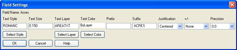
 Text Style: This allows you to set a text
style for the area labels. You can enter the name manually or use
the Select Style button to call up a dialog which presents a list
of known text styles.
Text Style: This allows you to set a text
style for the area labels. You can enter the name manually or use
the Select Style button to call up a dialog which presents a list
of known text styles.Below the Available and Used Fields
lists the following items for further controlling area label
generation:
Use Commas in Labels: This allows you to use commas in the
area labels.
Use MText: Check this box
to turn on the use of MText for area labels. If this is checked all
area labels will be grouped into as few MText entities as possible.
Area labels with different text styles, justification or layers
will not be combined into the same MText entity.
Erase Previous
Labels: When checked, previous area labels for the
area being relabeled will be erased.
Label Placement: When auto placement of
area labels is used, the labels can be placed either at the
centroid of area or at the rear side. This is accomplished by
selecting either the Center or Rear Side radio button,
respectively. When Center is selected the user can choose to have
the labels oriented according to the side lines of the area by
checking the Align By Sides checkbox. When either Align By Sides or
Rear Side is selected, the checkbox Flip Text for Twist Screen can
be selected to have the label rotated 180 degrees to present it in
the best reading orientation relative to the current Twist Screen
rotation setting.
Draw Symbol Around Lot
Description: When the Lot Description field is
included in the Used Fields list, the user can check this checkbox
to have a symbol drawn around the Lot Description field. When this
box is checked, you specify the symbol name in the Symbol Name field or click on the
current symbol (drawn to the right) to graphically choose the
desired symbol. You specify the layer by entering the name in the
Layer box or by clicking on
the Select button to choose
from a dialog that presents all known layers.
Symbol Buffer Offset: By
default, the symbol will be automatically scaled according to the
text length and size of the Lot Description value for the area. For
additional control of symbol scaling, the user can enter a number
in text size units in the Symbol Buffer Offset box. This value will
be added to the automatically generated default scaling value.
Avoid Label Overlap:
If this box is checked the area labels will be checked for overlaps
after they are generated. Please see the Overlap Manager
documentation for more information.
Overlap Settings: Click
this button to go to the Avoid Label Overlaps dialog where you can
review or modify the Overlap Manager settings. Please see the
Overlap Manager documentation for more information.
Table Process Settings Tab:
Use Area Tables: Use
this control to determine whether area labels are sent to a table
or not. Options are "Never", "Always" or "By Scaler".
To Table Area: When the
user has selected "By Scaler" in the "Use Area Tables" list this
item is enabled. When "By Scaler" is selected and the area is less
than this minimum, the area label is sent to a table.
Area Reference Numbering:
There are three different methods for setting the reference number:
Next Available will
automatically use the lowest available number. Specified With Prompt will prompt you
for a number for each area. Specified with Auto Numbering will
automatically use the lowest available number starting with the
specified number.
Auto Place Table
References: When checked, will automatically place the area
reference label according to the settings for the area labels as
specified in the Label Field and Settings tab (see above).
Otherwise you will be prompted to pick each label location
manually.
|
|
| The results of using a prefix with
square feet and acres |
Pulldown Menu Location: Area/Layout
Keyboard Command: defarea
Prerequisite: None
