 Horizontal
Scale: This is the horizontal scale for the current drawing.
This value can also be set by using the Drawing Setup command on
the Settings menu.
Horizontal
Scale: This is the horizontal scale for the current drawing.
This value can also be set by using the Drawing Setup command on
the Settings menu.
This command sets the defaults for the annotation menus and
controls the way various annotation commands work. Some of these
defaults can be changed globally by running Configure
command, which changes the file COGO.INI so that every time you
start Carlson, the new defaults are set. When this menu option is
selected the Annotate Defaults dialog appears.
This dialog is broken into 5 tabs: General, Angle, Distance,
Serial Lines and Parallel Lines.
General Tab
This tab is used for settings that apply to all annotation
types.
Horizontal
Scale: This is the horizontal scale for the current drawing.
This value can also be set by using the Drawing Setup command on
the Settings menu.
Text Size Scaler: This value is multiplied by the
horizontal scale value to set the text size units.
Text Offset Scaler: This value multiplied by the
horizontal scale defines the distance that an annotation label is
placed from its defining line.
Line Type Spacing: Specifies the distance between the
symbols on special line types.
Line Type Text Scaler: This value multiplied by the horizontal scale specifies the size of the symbols of special line types.
Arc Length Label: Specifies the prefix label for arc length labels.
Arc Text Spacing Factor: This variable controls how close letters will be spaced when labeling arcs. The lower the number, the closer the spacing. The higher, the farther apart. (The suggested range between 0.8 and 1.5)
Use MText: This option
creates the labels as MText instead of standard Text
entities.
Label Flip Tolerance
(degrees): Gives extra tolerance for label flipping for
readability. Labels draw in the north-west quadrant that are within
this number of degrees to due-north will be drawn upside
down.
Previous Labels:
Specifies if previous labels for the for the set of linework being
annotated are kept or deleted. Setting values are Retain, Erase,
Prompt Before Erasing.
Draw Leaders to Endpoints on Lines: This option creates
leader lines (crow's feet) between the distance annotation and the
line segment endpoints as shown below. These leaders are used to
help identify the endpoints that were used to create the distance
label.
 Distance Labels Only: When checked,
leaders will not be drawn unless the label includes a
distance.
Distance Labels Only: When checked,
leaders will not be drawn unless the label includes a
distance.
Leader Size Scaler: This option determines the maximum length for leaders. The size in drawing units will be the Leader Size Scaler multiplied by the Horizontal Scale (for example, 0.5x50=25). If the line segment is too short, the leader is shortened to fit.
Height Scaler: This option controls the height of the leader.
Offset Scaler: This option controls the distance between the line endpoints and the leader endpoints.
Arrow Scaler: This option controls the arrowhead size for leader styles with arrows.
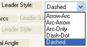
Leader Style: This option determines which of the five
styles of endpoint leaders to use. The five styles are: Arrow-Arc,
Arc-Arrow, Arc-Only, Dash-Dot and Dashed.
Draw Leaders to Endpoints on Arcs: This option creates
leader lines (crow's feet) between the arc segment endpoints as
shown below. These leaders are used to help identify the endpoints
that were used to create the arc label.
Leader Size Scaler: This option determines the maximum length for leaders. The size in drawing units will be the Leader Size Scaler multiplied by the Horizontal Scale (for example, 0.5x50=25). If the arc segment is too short, the leader is shortened to fit.
Offset Scaler: This option controls the distance between the arc endpoints and the leader endpoints.
Leader Style: This option determines which of the five
styles of endpoint leaders to use. The five styles are: Arrow-Arc,
Arc-Arrow, Arc-Only, Dash-Dot and Dashed.
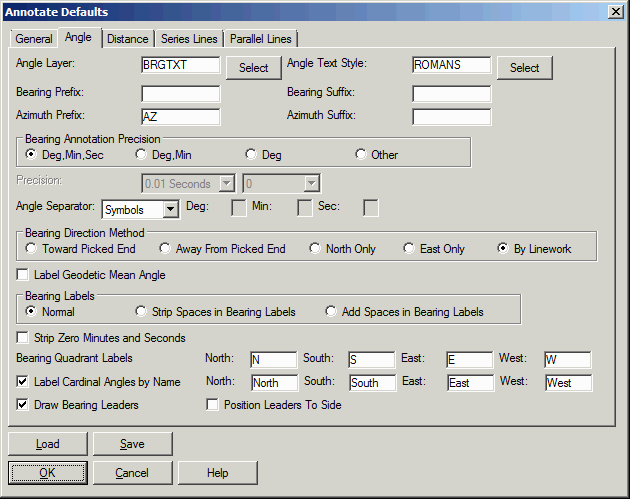 Angle Layer: This specifies
the layer to be used for angle labels.
Angle Layer: This specifies
the layer to be used for angle labels.
Angle Text Style: This specifies the text style to be
used for angle labels.
Bearing Annotation Precision: Specify the display
precision for bearing labels.
Angle Separator:
Choices are Symbol, Hyphen, Space, Other. When Other is chosen the
Deg. Min. and Sec. fields are enable to allow the user to enter
custom angle separators.
Bearing Direction Method: Choose the orientation of the bearing. This controls how lines selected for bearing or azimuth annotations will be referenced.
Toward Picked End: If this option is chosen, the line will be labeled in the direction of the endpoint that is closest to the point where you selected the line.
Away from Picked End: This labels the line in the direction away from the closest endpoint.
North Only: This option controls whether bearing
annotations will always be labeled in the north quadrants (NE or
NW) and never in the south quadrants.
East Only: This option controls whether bearing annotations will always be labeled in the east quadrants (NE or SE) and never in the west quadrants.
By Linework: This option labels the line in the direction that the line was drawn.
Label Geodetic Mean Angle: Instead of labeling the direct
coordinate bearing between two points, this option labels the
geodetic mean angle which is the average of the geodetic bearings
at the two points. This method converts the drawing coordinates to
lat/lon and calculates the convergence angles for both points. The
projection must be defined under Settings->Drawing
Setup.
Strip Spaces in Bearing Labels: This option causes the spaces in bearing labels to be removed.
Add Spaces in Bearing Labels: This option puts spaces
between the degree, minutes, and seconds numbers.
Strip Zero Minutes and
Seconds: This option shortens the label by dropping either
seconds and or minutes and seconds when they are equal to
zero.
Bearing Quadrant Labels:
These settings control the labels for the north/south prefix and
east/west suffix for bearing labels.
Label Cardinal Angles by
Name: When checked, the user is allowed to enter the labels
that will be used for each of the four cardinal angles.
Draw Bearing Leaders: This option creates a direction arrow with the bearing annotation as shown below.

Position Leaders To Side: This option draws the bearing
leader to the right side of the bearing label. Otherwise the leader
is drawn above the label.
Distance Tab
This tab is for settings that apply to distance
labels:
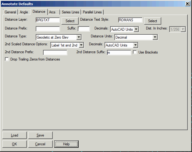 Distance Layer: This specifies the layer to be
used for distance labels.
Distance Layer: This specifies the layer to be
used for distance labels.
Distance Text Style: This specifies the text style to be
used for distance labels.
Distance Prefix and Suffix: These specify the prefix and
suffix that are added to distance annotations.
Decimals: The decimal places can be set to a specific
number or set to match the CAD units which are set by the LUPREC
system variable.
Distance In Inches: This controls the precision for
inches from 1/2 to 1/256th of an inch when the Distance Units is
set for inches.
Distance Type: This controls whether to label grid
distances or geodetic distances at zero or mean elevation. The
geodetic distances require the grid projection to be set in Drawing
Setup.
Distance Units: This
specifies the units used for distance labels. Choices are Decimal,
Chains, "Feet and Inches" and Both.
2nd Scaled Distance Options: This option labels
determines if a 2nd scaled distance is included in distance labels.
This 2nd distance is scaled by the Report Scale Factor set in the
Drawing Setup dialog. Choices for this option are "Label 1st
Only" (label distances in current drawing units only), "Label
1st and 2nd" (label distances in both current drawing units and
scaled by the Report Scale Factor) and "Label 2nd Only" (label
distances scaled by the Report Scale Factor Only). There are
separate settings for the 2nd Distance for the label prefix and
suffix and decimal places.
Label: This variable will be assigned as a suffix to the
second scaled distance label.
Drop Trailing Zeros in
Distances: This option allows you to drop trailing zeros on
distance labels.
Series Lines Tab
This tab is for settings that apply to Series Lines
labels (See the section "Auto Annotate" for a detailed description
of series line handling).
 Text Size Scaler: This value is multiplied by the
horizontal scale value to set the text size units for serial
lines.
Text Size Scaler: This value is multiplied by the
horizontal scale value to set the text size units for serial
lines.
Text Offset Scaler: This value multiplied by the
horizontal scale defines the distance that an annotation label is
placed from its defining line for serial lines.
Angle Layer: This specifies the layer to be used for
angle labels on serial lines.
Angle Text Style: This specifies the text style to be
used for angle labels on serial lines.
Distance Layer: This specifies the layer to be used for distance labels on serial lines.
Distance Text Style: This specifies the text style to be
used for distance labels on serial lines.
Parallel Lines Tab
This tab is for settings that apply to Parallel Lines
labels (See the section "Auto Annotate" for a detailed description
of parallel line handling).:
 Text Size Scaler: This value is multiplied by the
horizontal scale value to set the text size units for parallel
lines.
Text Size Scaler: This value is multiplied by the
horizontal scale value to set the text size units for parallel
lines.
Text Offset Scaler: This value multiplied by the horizontal scale defines the distance that an annotation label is placed from its defining line for parallel lines.
Angle Layer: This specifies the layer to be used for
angle labels on parallel lines.
Angle Text Style: This specifies the text style to be
used for angle labels on parallel lines.
Load/Save: Choose these options to load an existing annotation defaults file (.ADF) or save a new one, which will contain your current selections.
Pulldown Menu Location: Annotate
Keyboard Command: LDEF
Prerequisite: None